Opel Frontera UBS. Service manual — part 927
1B–102 AIR CONDITIONING
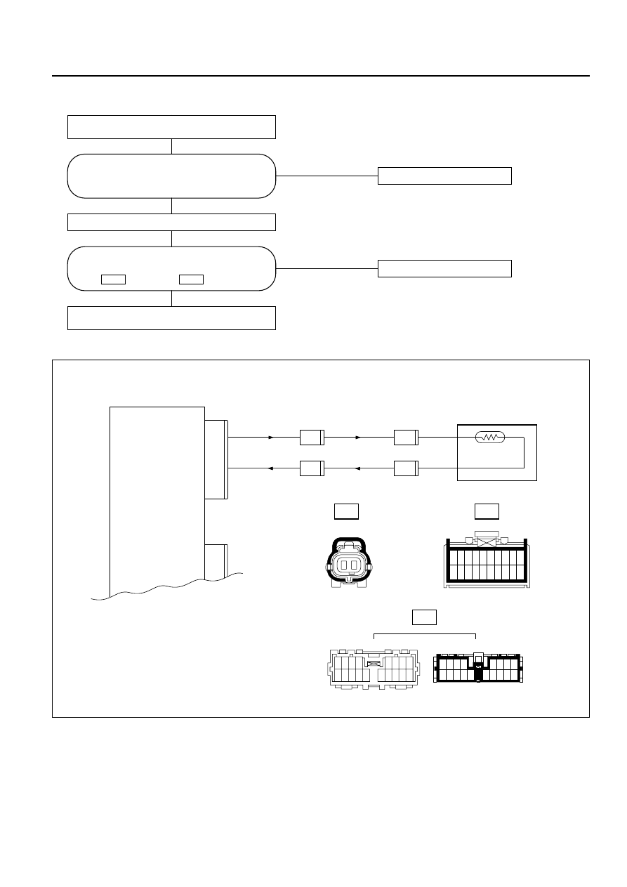
Chart 2: Ambient Sensor
NO
Replace the ambient sensor.
NO
Failure on the harness.
Connect the ambient sensor connector.
Replace the automatic heater/air conditioner
control unit.
YES
Disconnect the Ambient sensor connector
(C-86).
YES
Is performance of the ambient sensor
normal? (Refer to the later section on
"Check Up".)
Is resistance between the following
connectors normal?
No.2 and
No.11 .
I-33
I-33
I-33
C-86
H-24
1
11
2
12
3
13
4
14
5
15
6
16
7
17
8
18
9
19
10
20
0.3 LG/B
0.3 B/L
11
2
Ambient Sensor
Auto A/C Control Unit
(Ambient Sensor)
(Sensor GND)
I-33
0.3 LG/B
0.3 B/L
H-24
8
H-24
9
C-86
1
C-86
2
17 18
16
15
14
7 8
6
5
12 13
11
10
9
4
1
3
2
5
6
7
8
15
16
17
18
14
2
3
4
1
10
11
12
13
9
1
2
D08RY00176
AIR CONDITIONING 1B–103
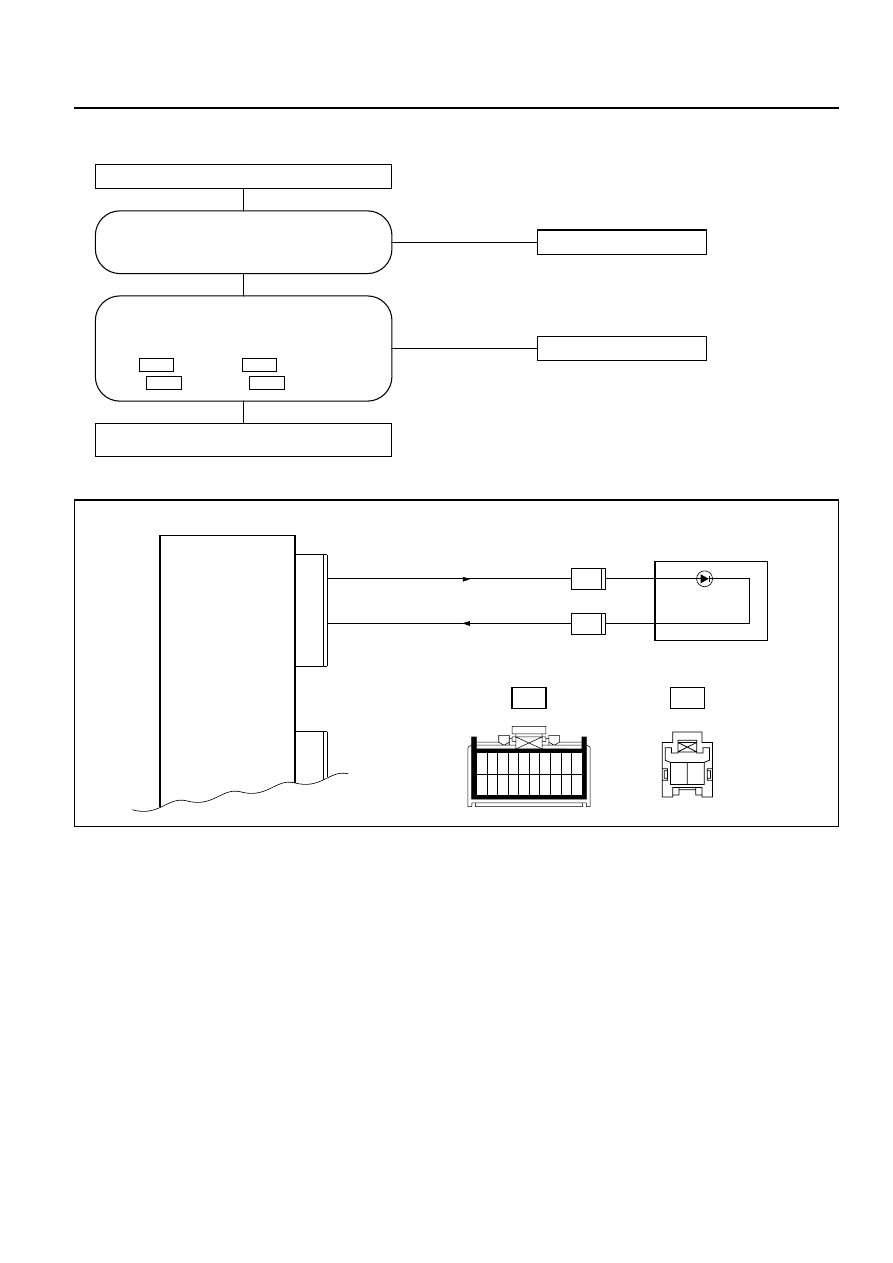
Chart 3: Sun Sensor
NO
Replace the sun sensor.
NO
Replace the harness.
Replace the automatic heater/air conditioner
control unit.
YES
Disconnect the sun sensor connector (I-35).
YES
Is performance of the sun sensor normal?
(Refer to the later section on "Check Up".)
Is the conduction provided between the
following chassis harness side connector
terminals?
No.3 and
No.1 .
No.11 and
No.2 .
I-35
I-33
I-35
I-33
0.3 LG/W
0.3 B/L
11
3
Sun Sensor
Auto A/C Control Unit
(Sun Sensor)
(Sensor GND)
I-33
I-35
1
I-35
2
I-33
I-35
2 1
1
11
2
12
3
13
4
14
5
15
6
16
7
17
8
18
9
19
10
20
D08RY00177
1B–104 AIR CONDITIONING
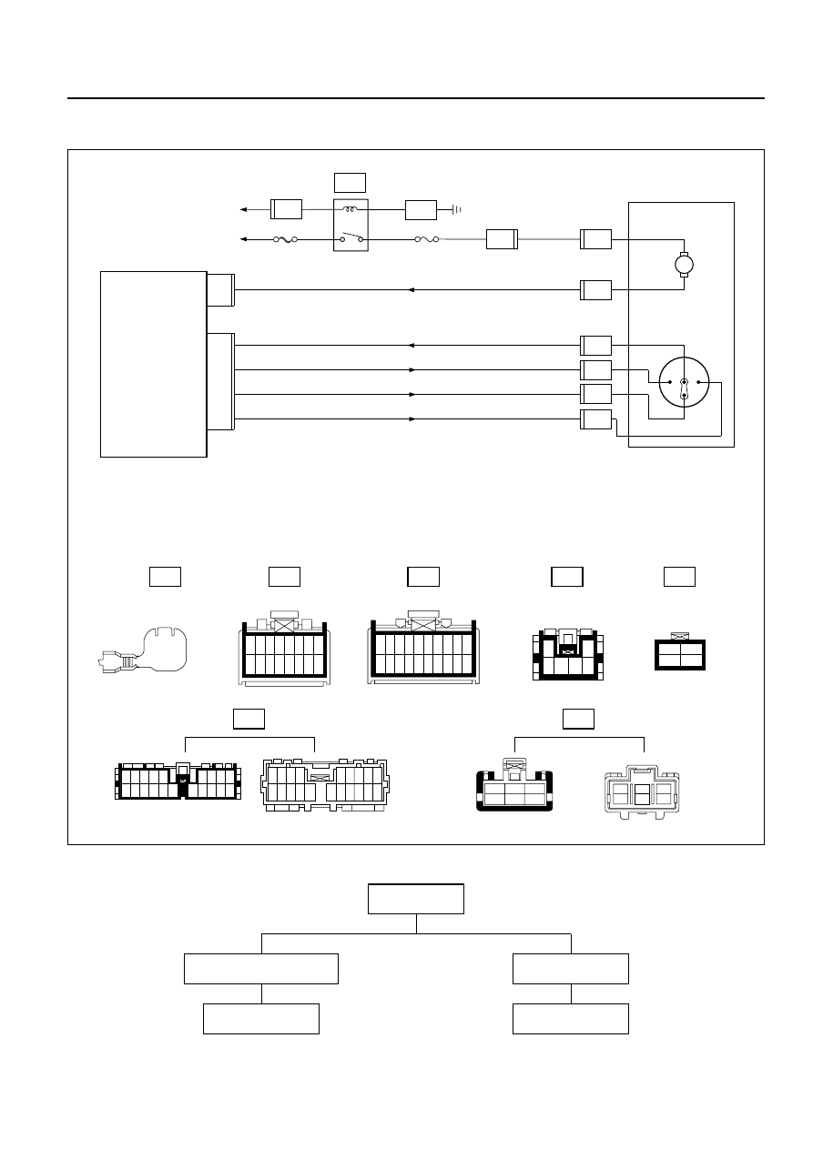
Inspection of the Intake Actuator System
B-19
I-32
B-36
H-26
H-13
I-49
I-33
1 2 3 4 5 6 7 8
9 10 11 12 13 14 15 16
1
11
2
12
3
13
4
14
5
15
6
16
7
17
8
18
9
19
10
20
10 11 12 13 14 15
1 2 3 4 5
17 18 19 20
6 7 8 9
16
9 8 7 6
20 19 18 17 16
5
14
15
4
13
3
12
2
11
1
10
B-36
1
2
3
4
M
FL-1 80A
MAIN
11
0.5 L/O
STARTER RELAY
I-33
11
12
13
14
0.3 L/R
0.5 L/W
0.3 B/L
0.3 L/Y
Intake Actuator
Auto A/C Control Unit
BATT.
(Intake Actuator)
GND(COM)
CIRC
FRESH
MIX
I-32
2
1
4
3
0.5 BR
0.5 BR
3.0 L/R
C-20 10A
A/C
I-49
3
H-13
10
I-49
4
I-49
5
I-49
6
I-49
1
I-49
2
H-26
14
B-19
1
3 4 5 6
2
3
6
2
5
1
4
1
2
3
4
5
6
Type of the
trouble
Control failure.
Chart B
Does not work at all.
Chart A
D08RY00178
AIR CONDITIONING 1B–105
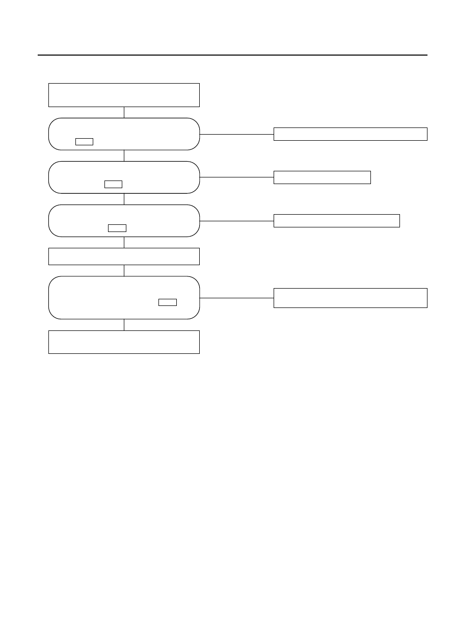
Chart A: Does Not Work At All
NO
Failure on the power supply circuit.
NO
Failure on the actuator.
NO
The harness is disconnected.
NO
Replace the automatic heater/air conditioner
control unit.
YES
YES
YES
YES
Turn on the ignition switch (the engine is
started).
Switch between the fresh air intake and the
interior air circulation.
Failure on the intake link unit (intake door
lock).
Is the battery voltage present between the
chassis harness side connector terminal
No.3
and the ground?
I-49
Is the battery voltage present between
the chassis harness side connector
terminal No.4
and the ground?
I-49
Is the battery voltage present between
the chassis harness side connector
terminal No.11
and the ground?
I-32
During the above switch operations, did
the voltage between the chassis harness
side connector terminal No.11
and
the ground go below 0.5V?
I-32
Нет комментариевНе стесняйтесь поделиться с нами вашим ценным мнением.
Текст