Opel Frontera UBS. Service manual — part 928
1B–106 AIR CONDITIONING
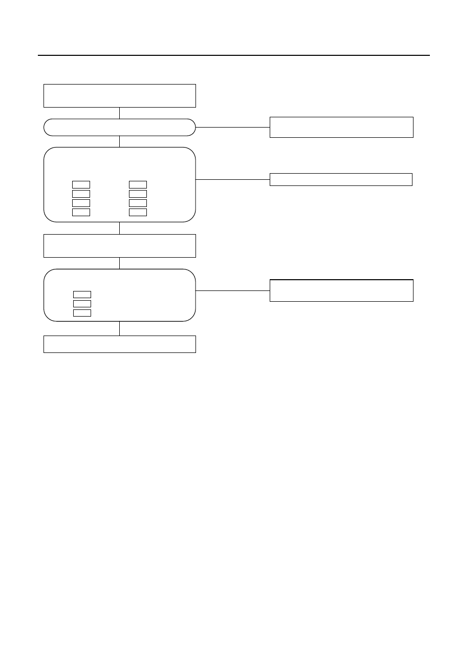
Chart B: Failure on the Intake Control
NO
The harness is disconnected.
NO
Failure on the automatic heater/air
conditioner control unit.
NO
Failure on the automatic heater/air
conditioner control unit.
YES
YES
YES
Turn on the ignition switch (the engine is
started).
Disconnect the intake actuator connector
(I-49).
Failure on the intake actuator.
Is the intake actuator stopped?
Is conduction provided between the
following chassis harness side connector
terminals?
No.5 and
No.11 .
No.6 and
No.12 .
No.1 and
No.13 .
No.2 and
No.14 .
I-33
I-49
I-33
I-49
I-33
I-49
I-33
I-49
Is voltage (approximately 5V) present
between the following?
No.12
and the ground.
No.13
and the ground.
No.14
and the ground.
I-33
I-33
I-33
AIR CONDITIONING 1B–107
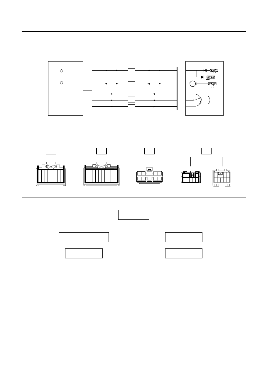
Inspection of the Mix Actuator System
H-67
I-32
I-33
1 2 3 4 5 6 7 8
9 10 11 12 13 14 15 16
1
11
2
12
3
13
4
14
5
15
6
16
7
17
8
18
9
19
10
20
I-45
I-32
M
6
6
0.3 V/W
I-33
11
3
0.5 B/L
5
7
0.3 V
15
2
0.3 V/G
5
23
20
6
16
24
8
0.3 V/R
I-45
3 KW
Heat
(Potentio Meter)
Cool
Cool
Heat
Mix Actuator
Auto A/C Control Unit
(
HEAT TO COOL
)
+
Cool side
+
Heat side
(
COOL TO HEAT
)
(
GND
)
(Mix Potentio Meter)
(+
5 V
)
4
5
8
7
6
0.3 V/W
0.3 B/L
0.3 V
0.3 V/G
H-67
H-67
H-67
H-67
H-67
0.3 V/R
1
2
5
6
3
4
8
9
7
1 2
3
8
4 5 6 7
1
2
3
8
4
5
6
7
Type of the
trouble
Control failure.
Chart B
Does not work at all.
Chart A
D08RY00179
1B–108 AIR CONDITIONING
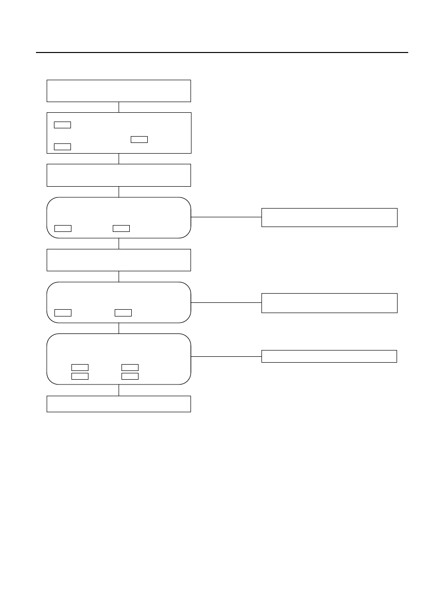
Chart A: Does Not work At All
NO
The harness is disconnected.
NO
Replace the automatic heater/air
conditioner control unit.
NO
Replace the automatic heater/air
conditioner control unit.
YES
YES
YES
Turn on the ignition switch (the engine is
started).
Disconnect the mix actuator connector
.
Short-circuit he chassis harness side
connector terminal No.3
and No.7
.
I-45
I-45
I-45
Using the temperature control lever,
select FC for the temperature.
Using the temperature control lever,
select FC for the temperature.
Failure on the actuator.
Is the battery voltage present on a regular
interval basis between the chassis
harness side connector terminals No.6
(+) and No.5
(-)?
I-32
I-32
Is conduction provided between the
following chassis harness side connector
terminals?
No.6 and
No.6 .
No.5 and
No.8 .
I-45
I-32
I-45
I-32
Is the battery voltage present on a regular
interval basis between the chassis
harness side connector terminals No.6
(-) and No.5
(+)?
I-32
I-32
AIR CONDITIONING 1B–109
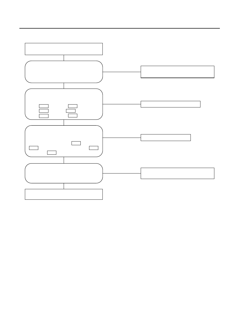
Chart B: Mix Actuator Control Failure
NO
Replace the actuator.
NO
The harness is disconnected.
NO
NO
Mix actuator control failure due to the
failed sensor.
YES
YES
YES
YES
Turn on the ignition switch (the engine is
started).
Replace the automatic heater/air conditioner
control unit.
Is conduction provided between the
following chassis harness side
connector terminals?
No.3 and
No.11 .
No.7 and
No.5 .
No.2 and
No.15 .
I-33
I-45
I-33
I-45
I-33
I-45
Is sum of the voltages between the
following chassis harness side connector
terminals approximately 5V?
Voltage between No.15
and No.5
plus voltage between No.5
and No.11
.
I-33
I-33
I-33
I-33
Does the self-diagnosis function (the
current trouble display) indicate failure
on the mix actuator potentiometer?
Is full stroke of the air mix door available
when you selected FH or FC using the
temperature control lever?
Failure on the air mix door or the link
unit.
Нет комментариевНе стесняйтесь поделиться с нами вашим ценным мнением.
Текст