Opel Frontera UBS. Service manual — part 926
1B–98 AIR CONDITIONING
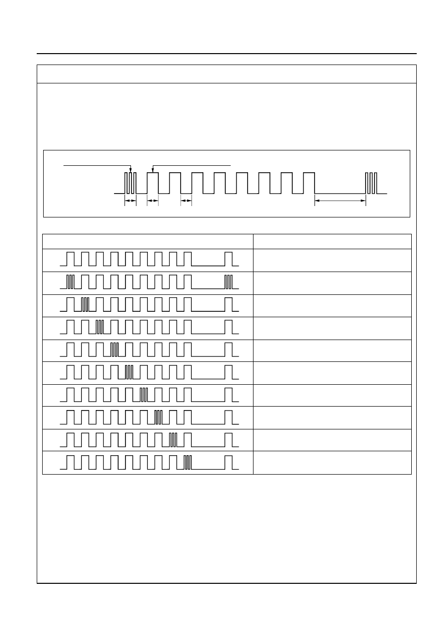
*1. Displaying the Current Trouble Diagnosing Table
Start the engine while holding down both the Auto switch and the DEF switch on the control panel, and
the table will appear in approximately 10 seconds to the indicator lamp (LED) of the air conditioning
switch. Result of the diagnosis along the following 9 items will be shown one by one in 0.5 second
interval irrespective of presence or absence of a trouble for a given item. When the display 9 items is
completed, it is repeated with 3 seconds of interval in between. A failed item is indicated by flashing of
the LED that is repeated 3 times within 0.5 seconds. If a trouble is indicated, you can locate the failed
section by knowing when in the total sequence it has been displayed.
Items for Current Trouble Diagnosis
As shown above, display of result along nine items is repeated with 3-second interval in between.
Note 1: When checking the solar radiation sensor, apply sufficient light using a 60W bulb.
Otherwise, it can be diagnosed as failed.
Note 2: If the temperature setting lever is set on both ends (one set to 18°C, blue scale = Full cool and
the other to 31°C, red scale = Full hot), they can be diagnosed as failed.
Note 3: Likewise, the fan switch can be diagnosed as failed if set on both ends.
LED on
LED off
Indication for presence
of a trouble
Indication for normal state
0.5
0.5
0.5
3 seconds interval
ON
OFF
Display pattern
Failed part
Normal pattern
In car sensor
Ambient sensor
Sun sensor (Note 1)
Duct sensor
Temperature control lever (Note 2)
Fan switch (Note 3)
Mix actuator
Mode (blow port) control
Intake (fresh air/interior air switching) control
F01RX010
F01RY00008
AIR CONDITIONING 1B–99
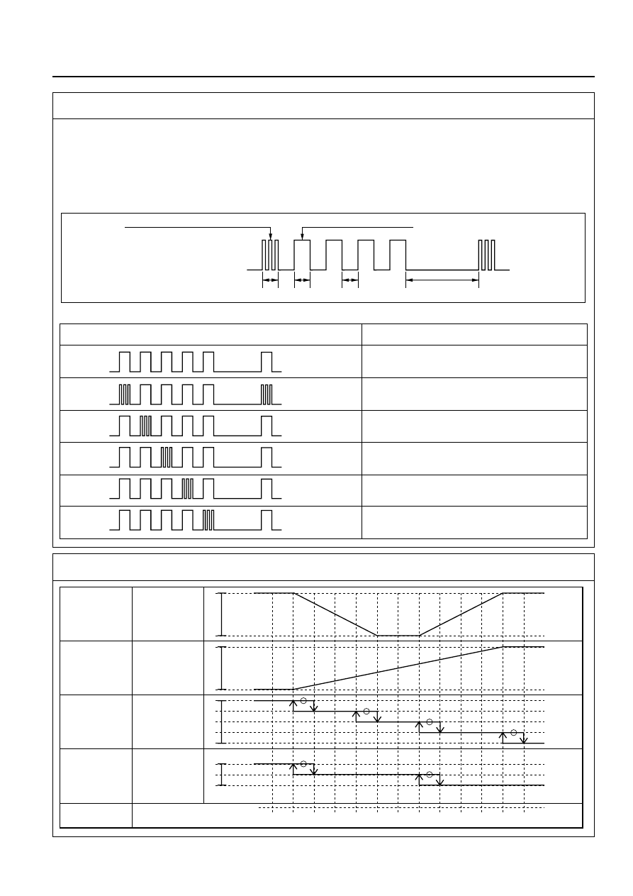
*2. Displaying the Past Trouble Diagnosing Table
The past trouble diagnosis displays only the items on which trouble has recurred 16 times in the past.
If you press the air conditioning switch once while the current trouble diagnosis is taking place, display
of the past trouble diagnosis will appear on the indicator lamp (LED) of the air conditioning switch.
Results of the diagnosis along the following five items are displayed one by one in 0.5 second interval
irrespective of presence or absence of a trouble. A failed item is indicated by flashing of the LED that is
repeated 3 times within 0.5 seconds. You can locate the failed section by counting in what sequence it
has been displayed.
Items for Past Trouble Diagnosis
LED on
LED off
Indication for presence of a trouble
Indication for normal state
0.5
0.5
0.5
3 second interval
Display pattern
ON
OFF
Normal pattern
In car sensor
Ambient sensor
Sun sensor
Duct sensor
Mix actuator
Failed part
F01RX011
F01RY00007
*3. Check of Output Equipment
FAN
MIX
MODE
DOOR
INTAKE
DOOR
SET UP
TEMPERATURE
100
(%)
33.5
F/H
VENT
B/L
FOOT
D/F
DEF
REC
MIX
FRE
F/C
20
21
22
23
24
25
26
27
28
29
30
F/H
(%)
F/C
F01RY00001
1B–100 AIR CONDITIONING
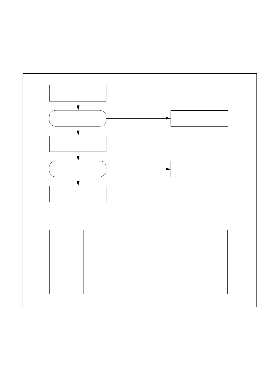
Independent check of sensors
Replace the control unit.
Sensors
Allowable range
Check method
In car sensor
Ambient sensor
Sun sensor
Refer to the sensor resistance curve.
Refer to the sensor resistance curve.
100 ohms maximum in forward and 0.02 mA
minimum when exposed to 60W incandescent lamp.
Chart 1
Chart 2
Chart 3
Replace the harness and
connector.
Replace the sensors.
Check the related harness and
connector
Normal ?
Normal ?
NO
NO
YES
YES
INSPECTION BY FAILED LOCATION
Inspection of the Sensors
When the self-diagnosis function has determined that trouble is present on the sensors, check them
according to the following flow chart.
F01RY00005
AIR CONDITIONING 1B–101
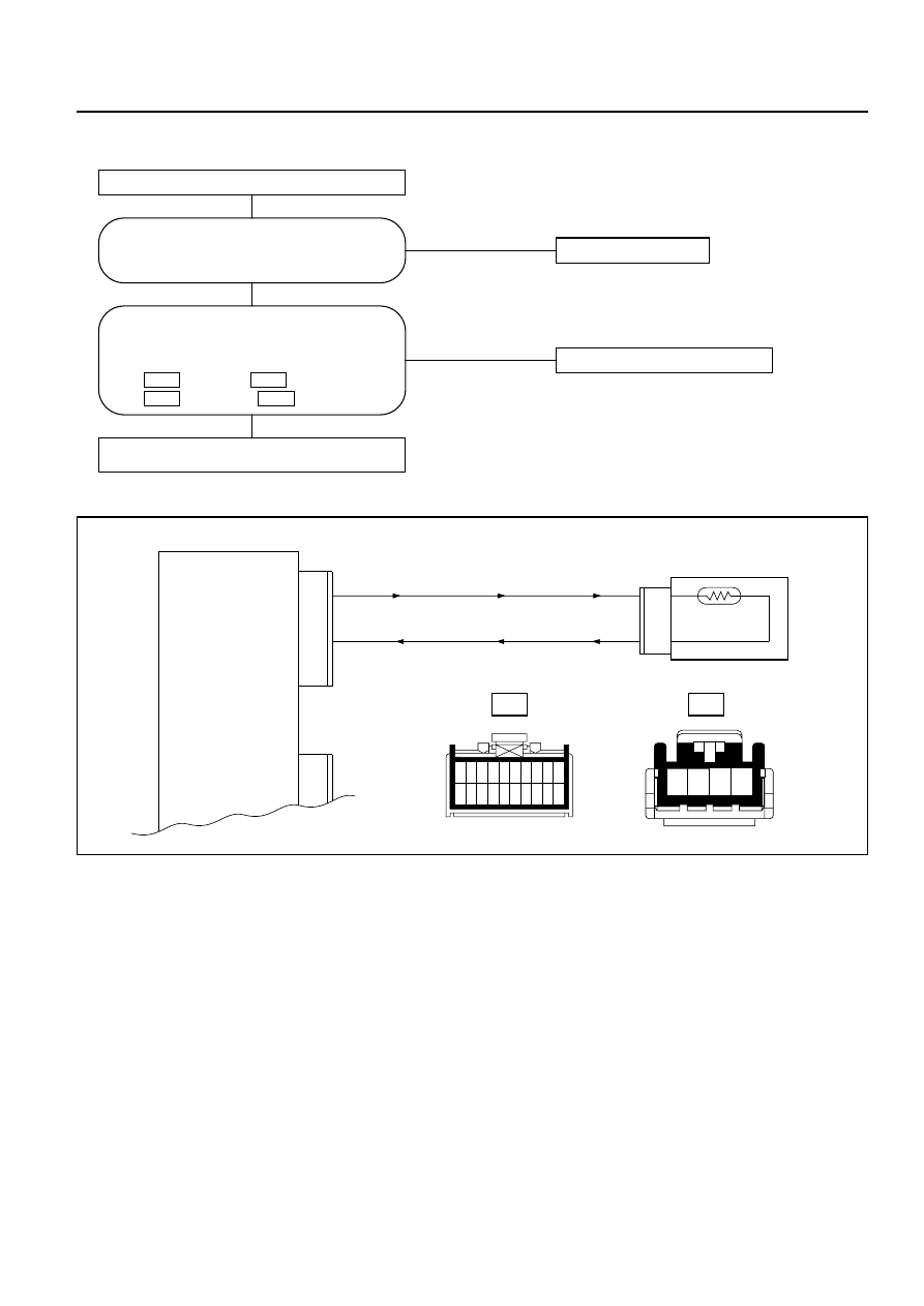
Chart 1: In Car Sensor
NO
Replace the sensor.
NO
Disconnection of the harness.
Failure on the automatic heater/air
conditioner control unit.
YES
Disconnect the in car sensor connector (I-34).
YES
Is the sensor performance normal? (refer to
the later section on "Check Up")
Are conduction provided between the
following connector terminals on chassis
harness side?:
No.3 and
No.1 .
No.4 and
No.11 .
I-33
I-34
I-33
I-34
I-33
I-34
1
11
2
12
3
13
4
14
5
15
6
16
7
17
8
18
9
19
10
20
0.3 BR/B
0.5 B/L
11
1
In car Sensor
Auto A/C Control Unit
(In car Sensor)
(Sensor GND)
4
3
I-33
I-34
1 2
4
3
D08RY00174
Нет комментариевНе стесняйтесь поделиться с нами вашим ценным мнением.
Текст