Opel Frontera UBS. Service manual — part 1510

7A1–70 TRANSMISSION CONTROL SYSTEM (4L30–E)
Diagnostic Aids
D
Inspect the wiring for poor electrical connection at the
PCM and at the transmission 16–way connector.
Look for possible bent, backed out, deformed or
damaged terminals. Check for weak terminal tension
as well. Also check for a chafed wire that could short
to bare metal or other wiring. Inspect for a broken wire
inside the insulation.
D
When diagnosing for a possible intermittent short or
open condition, move the wiring harness while
observing test equipment for a change.
Test Description
The numbers below refer to the step numbers on the
diagnostic chart:
2. This test checks for power to the brake band apply
solenoid from the ignition through the PCM.
3. This test checks the resistance of the transmission
internal wiring harness and brake band apply
solenoid.
4. This test checks the ability of the PCM and wiring to
control the ground circuit.
DTC P1850 Brake Band Apply Solenoid Malfunction
Step
Action
Yes
No
1
1. Install the scan tool.
2. With the engine “on”, turn the ignition switch “on”.
NOTE: Before clearing DTC(s), use the scan tool to record “Failure
Records” for reference, as data will be lost when the “Clear Info”
function is used.
3. Record the DTC “Failure Records”.
Were DTCs P0753, P0758 set?
Go to Step 2
Go to Step 3
2
Using the J39200 DVOM, back probe between PCM connector
terminals J3–E14 and J2–C8.
Is the voltage between 10 to 12 volts?
Go to Step 4
Go to Step 5
3
1. Turn the ignition “off”.
2. Disconnect the J1 (RED) and J3 (BLUE) PCM connectors.
3. Using the J39200 DVOM, measure the resistance between
PCM connector terminals J1–A16 and J3–E14.
Is the resistance within 10–12 ohms?
Go to Step 11
Go to Step 12
4
Using the J39200 DVOM, back probe between PCM connector
terminals J1–A16 and J2–C8.
Is the voltage between 10 to 12 volts?
Go to Step 25
Go to Step 3
5
1. Turn the ignition “off”.
2. Disconnect the J1 (RED) and J3 (BLUE) PCM connectors.
3. Using the J39200 DVOM, check continuity between PCM
terminal J3–E14 and ground.
Is there a continuity?
Go to Step 6
Go to Step 8
6
1. Disconnect the transmission 16–way connector H–53.
2. Using the J39200 DVOM, check continuity between connector
H53–13 and ground.
Is there a continuity?
Go to Step 7
Go to Step 16
7
1. Disconnect the transmission main case connector M–7.
2. Using the J39200 DVOM, check continuity between the
terminal M7–2(B) and ground.
Is there a continuity?
Go to Step 17
Go to Step 18
8
1. Disconnect the J1 (RED) PCM Connector.
2. Using the J39200 DVOM, measure the resistance between
PCM connector terminals J1–A16 and J3–E14.
Is the resistance within 10–12 ohms?
Go to Step 25
Go to Step 9
9
1. Disconnect the transmission 16–way connector H–53.
2. Using the J39200 DVOM, measure the resistance between
terminal H53–13 and H53–15.
Is the resistance within 10–12 ohms?
Go to Step 16
Go to Step 10

TRANSMISSION CONTROL SYSTEM (4L30–E)
7A1–71
DTC P1850 Brake Band Apply Solenoid Malfunction (Cont’d)
Step
No
Yes
Action
10
1. Disconnect the transmission main case connector M–7.
2. Using the J39200 DVOM, measure the resistance between
terminals M7–2(B) and M7–4(C).
Is the resistance within 10–12 ohms?
Go to Step 19
Go to Step 20
11
Using the J39200 DVOM, check continuity between PCM
terminal J1–A16 and ground.
Is there a continuity?
Go to Step 13
Go to Step 25
12
1. Disconnect the transmission 16–way connector H–53.
2. Using the J39200 DVOM, measure the resistance between
terminal H53–13 and H53–15.
Is the resistance within 10–12 ohms?
Go to Step 23
Go to Step 14
13
1. Disconnect the transmission 16–way connector H–53.
2. Using the J39200 DVOM, check continuity between terminal
H53–13 and ground.
Is there a continuity?
Go to Step 15
Go to Step 21
14
1. Disconnect the transmission main case connector M–7.
2. Using the J39200 DVOM, measure the resistance between
terminals M7–2(B) and M7–4(C).
Is the resistance within 10–12 ohms?
Go to Step 24
Go to Step 20
15
1. Disconnect the transmission main case connector M–7.
2. Using the J39200 DVOM, check continuity between the
terminal M7–2(B) and ground.
Is there a continuity?
Go to Step 17
Go to Step 22
16
The wiring harness between PCM terminal J3–E14 and
transmission 16–way connector terminal H53–15 is open.
Was a problem found and corrected?
Go to Step 26
—
17
The brake band apply solenoid is faulty, or the internal wiring
harness from the brake band apply solenoid is shorted to ground.
Was a problem found and corrected?
Go to Step 26
—
18
The wiring harness between the transmission 16–way connector
terminal H53–15 and the transmission main case connector
terminal M7–4(C) is shorted to ground.
Was a problem found and corrected?
Go to Step 26
—
19
The wiring harness between the transmission 16–way connector
terminal H53–15 and the transmission main case connector
terminal M7–4(C) is open.
Was a problem found and corrected?
Go to Step 26
—
20
The brake band apply solenoid is faulty, or the internal wiring
harness from the brake band apply solenoid is open.
Was a problem found and corrected?
Go to Step 26
—
21
The wiring harness between the PCM connector terminal J1–A16
and transmission 16–way connector terminal H53–13 is shorted
to ground.
Was a problem found and corrected?
Go to Step 26
—
22
The wiring harness between the transmission 16–way connector
terminal H53–13 and the transmission main case connector
terminal M7–2(B) is shorted to ground.
Was a problem found and corrected?
Go to Step 26
—

7A1–72 TRANSMISSION CONTROL SYSTEM (4L30–E)
DTC P1850 Brake Band Apply Solenoid Malfunction (Cont’d)
Step
No
Yes
Action
23
The wiring harness between the PCM connector terminal J1–A16
and the 16–way connector terminal H53–13 is open.
Was a problem found and corrected?
Go to Step 26
—
24
The wiring harness between the transmission 16–way connector
terminal H53–13 and the transmission main case connector
terminal M7–2(B) is open.
Was a problem found and corrected?
Go to Step 26
—
25
Check every connection at the PCM.
If OK, replace the PCM. Refer to Powertrain Control Module
(PCM) in Automatic Transmission (4L30–E) section.
Is the replacement complete?
Go to Step 26
—
26
1. After the repair is complete, use the scan tool to select “DTC”,
then “Clear Info” function and ensure the following conditions
are met:
D
The brake band apply solenoid is commanded “on” and the
volts drop to zero.
D
The brake band apply solenoid is commanded “off” and the
volts increase to B+.
2. Review the scan tool “DTC Info”.
Has the last test failed or is the current DTC displayed?
Begin diagnosis
again
Go to Step 1
Repair verified
Exit DTC table
TRANSMISSION CONTROL SYSTEM (4L30–E)
7A1–73
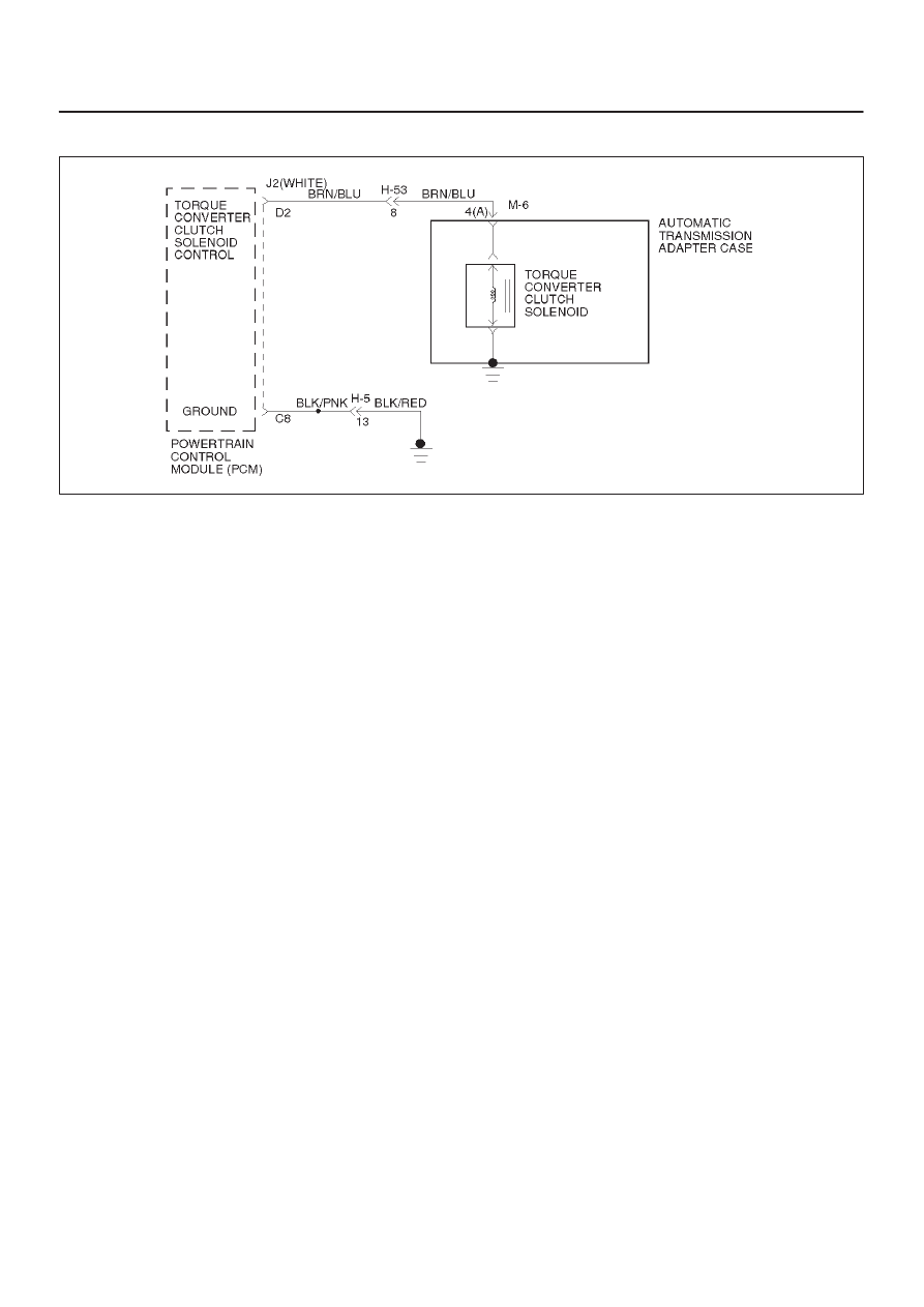
DTC P1860 TCC Solenoid Electrical
D07RW010
Circuit Description
The PCM allows current to flow through the solenoid coil
according to the duty cycle (percentage of “on” and “off”
time). This current flow through the solenoid coil creates
a magnetic field that magnetizes the solid core. The
magnetized core attracts the check ball to seat against
spring pressure. This blocks the exhaust for the TCC
signal fluid and allows 2–3 drive fluid to feed to TCC signal
circuit. The TCC signal fluid pressure acts on the TCC
regulator valve to regulate line pressure and to apply fluid
pressure to the torque converter clutch shift valve. When
the TCC shift valve is in the apply position, regulated
apply fluid pressure is directed through the TCC valve to
apply the torque converter clutch. The TCC solenoid is
used in conjunction with the TCC solenoid to regulate fluid
to the torque converter. The TCC solenoid is attached to
the valve body within the transmission.
This DTC detects a continuous open or short to ground or
ignition in the TCC circuit or the TCC solenoid. This is a
type “D” DTC.
Conditions For Setting The DTC
D
Battery voltage is between 10 and 16 volts.
D
No shift solenoid A DTC P0753.
D
No shift solenoid B DTC P0758.
D
Ignition is “on”, Engine “run”.
D
The PCM commands the solenoid “on” and the
voltage remains low (zero volts).
D
The PCM commands the solenoid “off” and the
voltage remains high (B+).
D
All conditions met for 0.25 seconds.
Action Taken When The DTC Sets
D
Inhibit TCC engagement.
D
The PCM will not illuminate the CHECK TRANS
Lamp.
Conditions For Clearing The DTC
D
The DTC can be cleared from the PCM history by
using a scan tool.
D
The DTC will be cleared from history when the vehicle
has achieved 40 warmup cycles without a failure
reported.
D
The PCM will cancel the DTC default actions when
the fault no longer exists and the ignition is cycled “off”
long enough to power down the PCM.
Diagnostic Aids
D
Inspect the wiring for poor electrical connections at
the PCM and at the transmission 16–way connector.
Look for possible bent, backed out, deformed or
damaged terminals. Check for weak terminal tension
as well. Also check for a chafed wire that could short
to bare metal or other wiring. Inspect for a broken wire
inside the insulation.
D
When diagnosing for a possible intermittent short or
open condition, move the wiring harness while
observing test equipment for a change.
Test Description
The numbers below refer to the step numbers on the
diagnostic chart:
2. This test checks for voltage to the solenoid.
3. This test checks the ability of the PCM and wiring to
control the ignition circuit.
8. This test checks the resistance of the TCC solenoid
and the internal wiring harness.
Нет комментариевНе стесняйтесь поделиться с нами вашим ценным мнением.
Текст