Opel Frontera UBS. Service manual — part 97
FRONT SUSPENSION 3C – 23
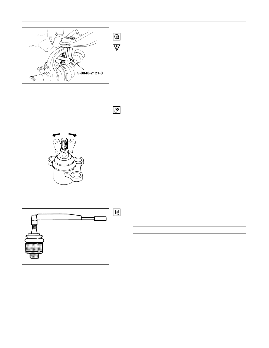
1. Nut and Cotter Pin
Remove the upper ball joint from the knuckle.
Remover: 5-8840-2121-0 (J-36831)
CAUTION:
Be careful not t o break the ball joint boot.
2. Bolt, Nut and Washer
3. Upper Ball Joint
INSPECTION AND REPAIR
Make necessary parts replacement if wear, damage,
corrosion or any other abnormal conditions are found
through inspection.
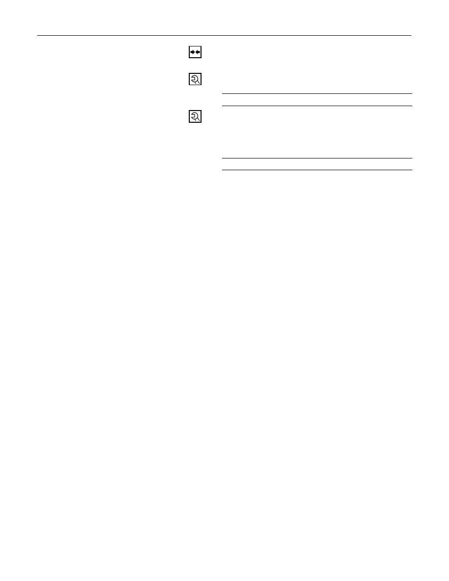
Inspect the lower end boot for damage or grease leak.
Move the ball joint as shown in the figure to confirm its
normal movement.
Inspect screw/taper area of ball for flaws.
If any defects are found by the above inspections, replace
the ball joint assembly with new one.
After moving the ball joint 4 or 5 times, attach nut then
measure the preload.
Upper Ball Joint Preload
N·m (kg·m/lb·in)
0.5 – 3.2 (0.05 – 0.33 / 4.3 – 28.6)
If the above limits specified are exceeded, replace the
ball joint assembly.
3C – 24 FRONT SUSPENSION
INSTALLATION
3. Upper Ball Joint
2. Bolt, Nut and Washer
Upper Ball Joint Bracket Nut Torque
N·m (kg·m/lb·ft)
57 (5.8 / 42)
1. Nut and Cotter Pin
Tighten the nut to the specified torque with just
enough additional torque to align cotter pin holes.
Install new cotter pin.
Upper Ball Joint Nut Torque
N·m (kg·m/lb·ft)
98 (10.0 / 72)
FRONT SUSPENSION 3C – 25
LOWER BALL JOINT
Removal Steps
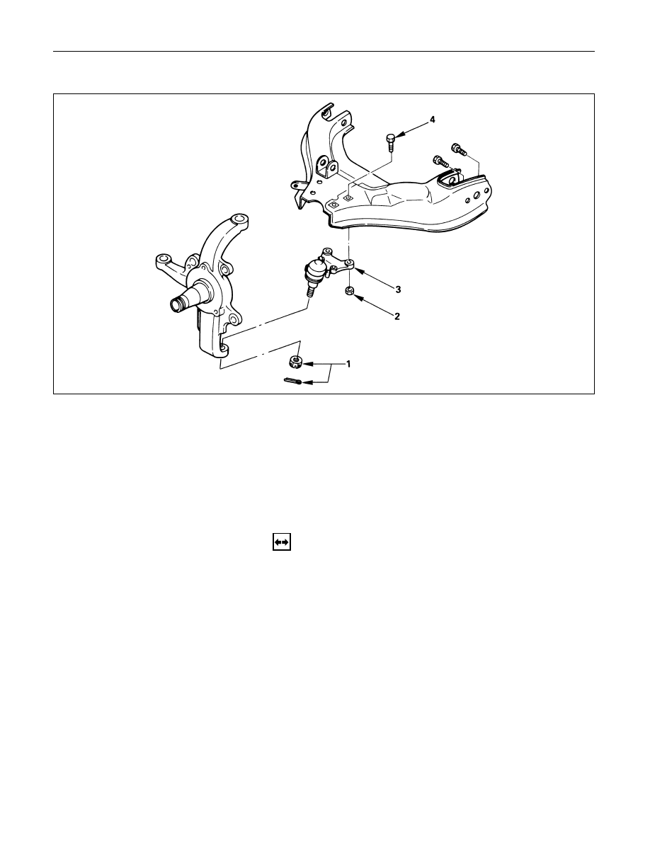
1.
Nut and cotter pin
2.
Nut
3.
Lower ball joint
4.
Bolt
Installation Steps
4.
Bolt
3.
Lower ball joint
2.
Nut
1.
Nut and cotter pin
REMOVAL
Preparation:
1)
Raise the vehicle and support the frame with suitable
safety stands.
2)
Remove wheel and tire assembly. Refer to “Wheels
and Tires” in section 3E.
3)
Remove the outer track rod from the knuckle. Refer to
“Steering Linkage” in section 2A.
4)
Remove the retaining ring from the front axle driving
shaft to release the shaft from hub. Refer to “Front
Axle” in section 4C.
5)
Support lower control arm with a jack.
3C – 26 FRONT SUSPENSION
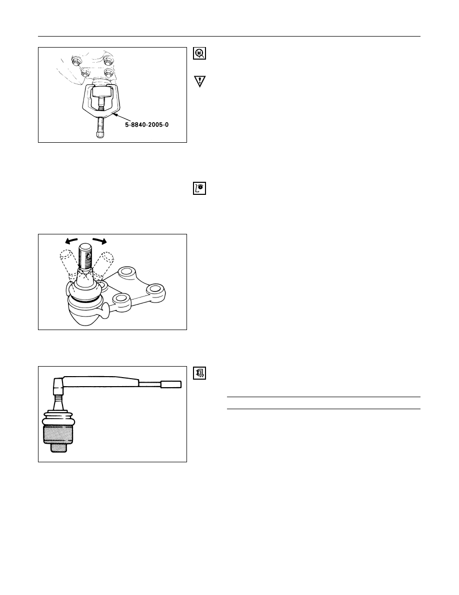
1. Nut and Cotter Pin
Remove the upper ball joint from the knuckle.
Remover: 5-8840-2005-0 (J-29107)
CAUTION:
Be careful not to break the ball joint boot.
2. Nut
3. Lower Ball Joint
4. Bolt
INSPECTION AND REPAIR
Make necessary parts replacement if wear, damage,
corrosion or any other abnormal conditions are found
through inspection.
Inspect the lower end boot for damage or grease leak.
Move the ball joint as shown in the figure to confirm its
normal movement.
Inspect screw/taper area of ball for flaws.
If any defects are found by the above inspections, replace
the ball joint assembly with new one.
After moving the ball joint 4 or 5 times, attach nut then
measure the preload.
Lower Ball Joint Preload
N·m (kg·m/lb·in)
0.5 – 6.4 (0.05 – 0.65 / 4.3 – 56.4)
If the above limits specified are exceeded, replace the
ball joint assembly.
Нет комментариевНе стесняйтесь поделиться с нами вашим ценным мнением.
Текст