Opel Frontera UBS. Service manual — part 95
FRONT SUSPENSION 3C – 15
REMOVAL
Preparation:
1)
Raise the vehicle and support the frame with suitable
safety stands.
2)
Remove wheel and tire assembly. Refer to “Wheels
and Tires” in section 3E.
3)
Remove the brake caliper and disconnect flexible hose.
Refer to “Brakes” in section 5.
4)
Support lower control arm with a jack.
1. Speed Sensor Cable (if equipped with ABS)
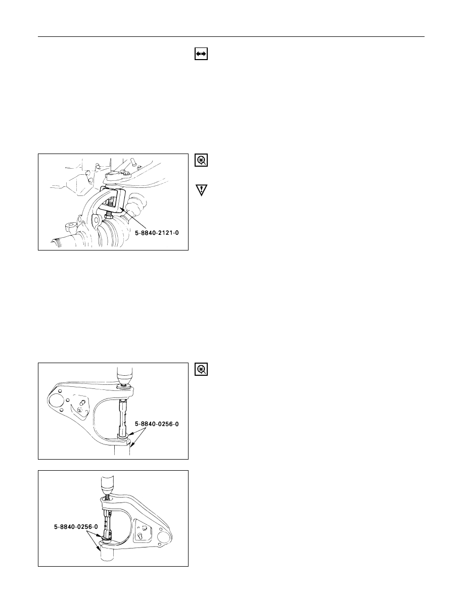
2. Nut and Cotter Pin
Remove the upper ball joint from the knuckle.
Remover: 5-8840-2121-0 (J-36831)
CAUTION:
Be careful not to break the ball joint boot.
3. Upper Ball Joint
4. Bolt and Plate
5. Nut Assembly
6. Camber Shims
Note the positions and number of shims.
7. Caster Shims
Note the positions and number of shims.
8. Upper Control Arm Assembly
9. Nut
10. Plate
11. Bushing
Remover: 5-8840-0256-0 (J-29755)
12. Fulcrum Pin
3C – 16 FRONT SUSPENSION
INSPECTION AND REPAIR
Make necessary parts replacement if wear, damage,
corrosion or any other abnormal conditions are found
through inspection.
Check the following parts:
•
Upper control arm
•
Bushing
•
Fulcrum pin
INSTALLATION
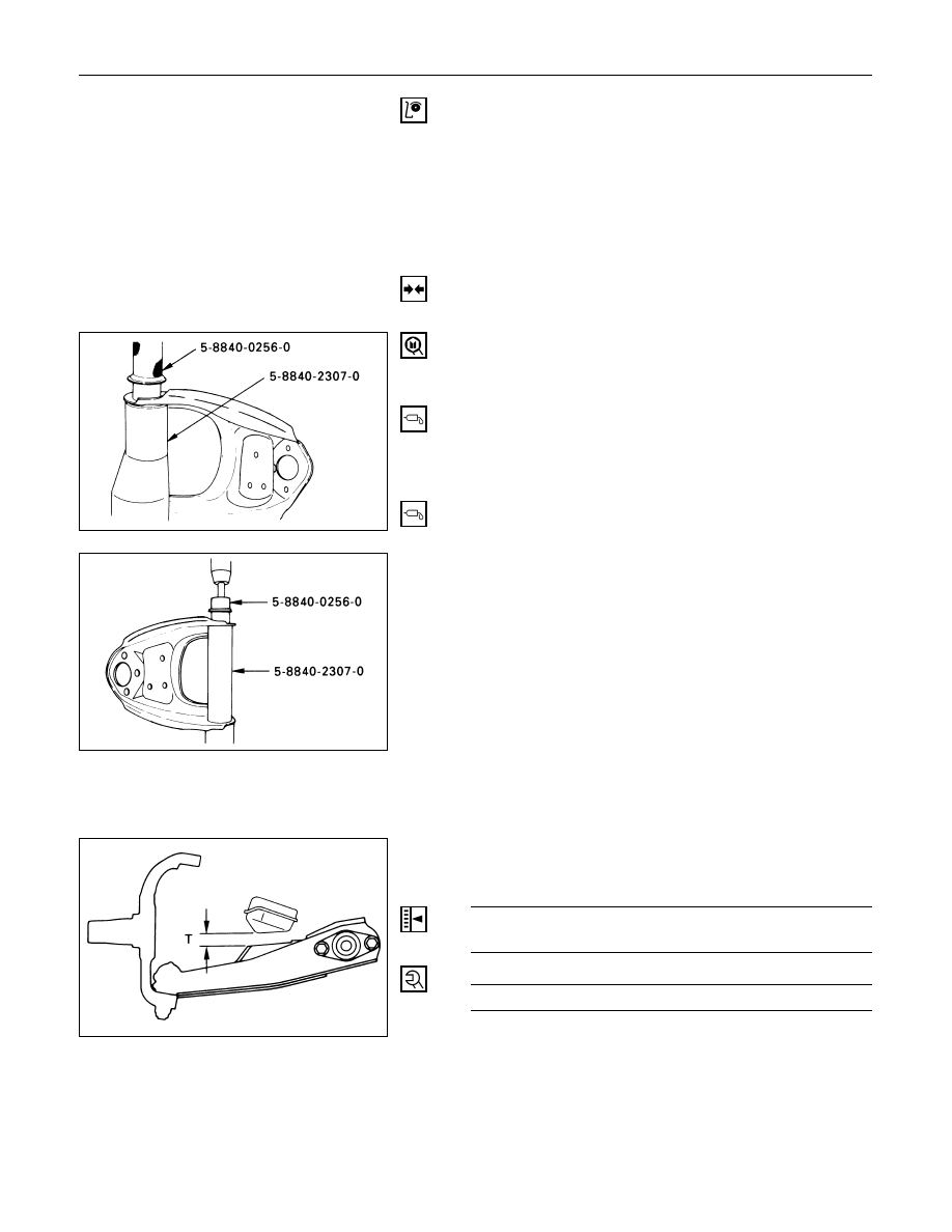
12. Fulcrum Pin
11. Bushing
Installer: 5-8840-0256-0 (J-29755) and
5-8840-2307-0 (J-39376)
10. Plate
9. Nut
Tighten fulcrum pin nut finger-tight.
NOTE:
Torque fulcrum pin nut after adjusting buffer clearance.
Buffer Clearance (T)
mm (in)
23 (0.91) Wide Tread
24 (0.94) Narrow Tread
Fulcrum Pin Nut Torque
N·m (kg·m/lb·ft)
108 (11.0 / 80)
FRONT SUSPENSION 3C – 17
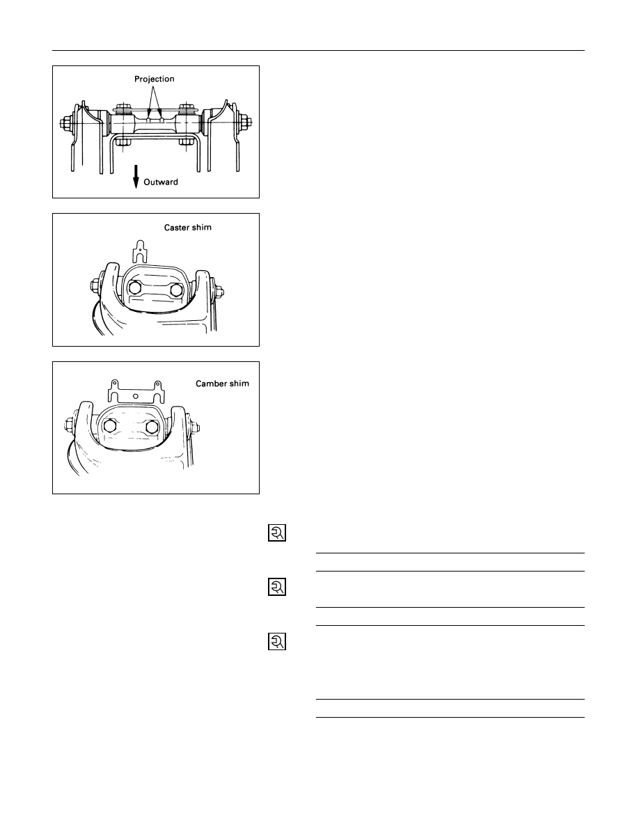
8. Upper Control Arm Assembly
Install upper control arm assembly with the fulcrum
pin projections turned inward.
7. Caster Shims
Install the caster shims between the chassis frame and
fulcrum pin.
6. Camber Shims
Install the camber shims between the chassis frame
and fulcrum pin.
5. Nut Assembly
4. Bolt and Plate
Fulcrum Pin Bolt Torque
N·m (kg·m/lb·ft)
152 (15.2 / 112)
3. Upper Ball Joint
Upper Ball Joint Nut Torque
N·m (kg·m/lb·ft)
57 (5.8 / 42)
2. Nut and Cotter Pin
Tighten the nut to the specified torque, with just
enough additional torque to align cotter pin holes.
Install new cotter pin.
Upper Ball Joint Nut Torque
N·m (kg·m/lb·ft)
98 (10.0 / 72)
1. Speed Sensor Cable (if equipped with ABS)
3C – 18 FRONT SUSPENSION
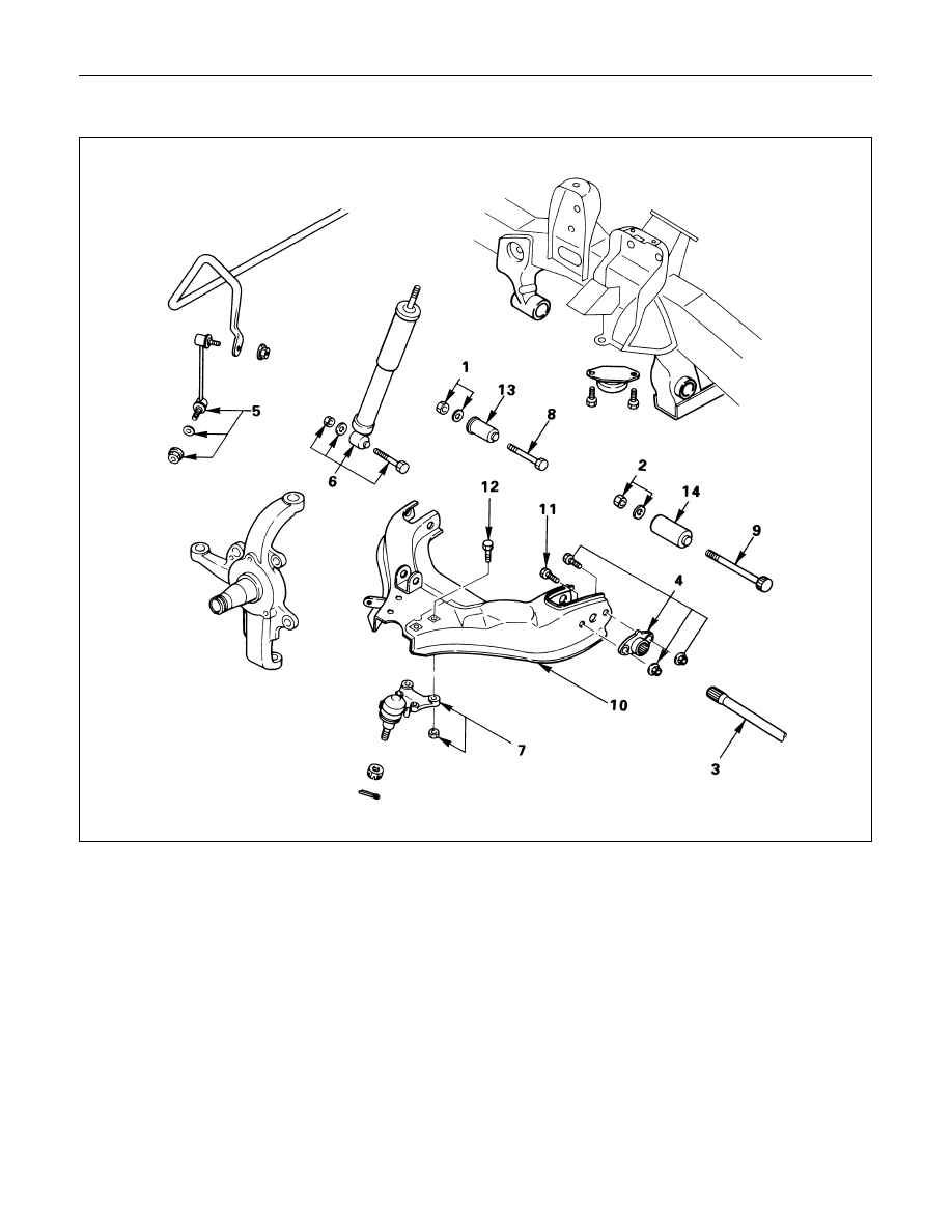
LOWER CONTROL ARM
Removal Steps
1.
Nut and washer, front
2.
Nut and washer, rear
3.
Torsion bar
4.
Torsion bar arm
5.
Stabilizer link
6.
Shock absorber
7.
Lower ball joint
8.
Bolt, front
9.
Bolt, rear
10.
Lower control arm
11.
Bolt, torsion bar arm
12.
Bolt, lower ball joint
13.
Bushing, front
14.
Bushing, rear
Installation Steps
14.
Bushing, rear
13.
Bushing, front
12.
Bolt, lower ball joint
11.
Bolt, torsion bar arm
10.
Lower control arm
9.
Bolt, rear
8.
Bolt, front
7.
Lower ball joint
6.
Shock absorber
5.
Stabilizer link
4.
Torsion bar arm
3.
Torsion bar
2.
Nut and washer, rear
1.
Nut and washer, front
Нет комментариевНе стесняйтесь поделиться с нами вашим ценным мнением.
Текст