Infiniti G20 (P11). Manual — part 287
DTC Confirmation Procedure
NCEC0620
NOTE:
If “DTC Confirmation Procedure” has been previously conducted,
always turn ignition switch “OFF” and wait at least 10 seconds
before conducting the next test.
SEF195Y
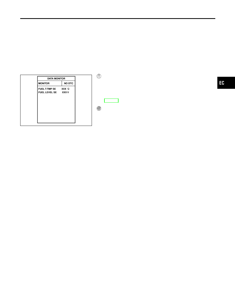
WITH CONSULT-II
NCEC0620S01
1)
Turn ignition switch “ON”.
2)
Select “DATA MONITOR” mode with CONSULT-II.
3)
Wait at least 5 seconds.
4)
If 1st trip DTC is detected, go to “Diagnostic Procedure”,
EC-561.
WITH GST
NCEC0620S02
Follow the procedure “WITH CONSULT-II” above.
GI
MA
EM
LC
FE
CL
MT
AT
AX
SU
BR
ST
RS
BT
HA
SC
EL
IDX
DTC P1464 FUEL LEVEL SENSOR CIRCUIT (GROUND SIGNAL)
DTC Confirmation Procedure
EC-559
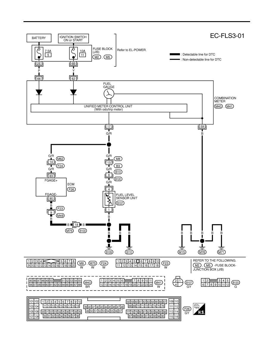
Wiring Diagram
NCEC0621
TEC832
DTC P1464 FUEL LEVEL SENSOR CIRCUIT (GROUND SIGNAL)
Wiring Diagram
EC-560
Diagnostic Procedure
=NCEC0622
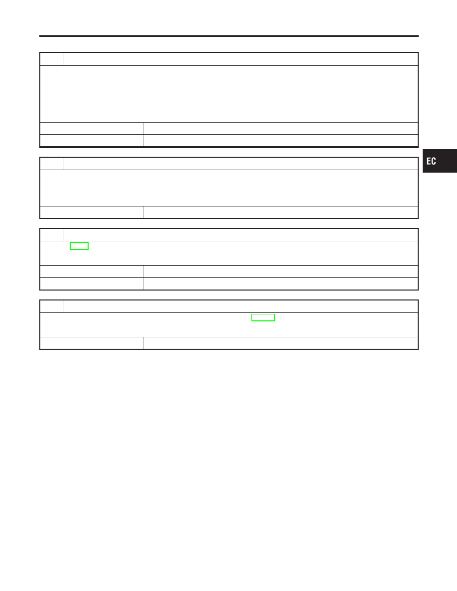
1
CHECK FUEL LEVEL SENSOR GROUND CIRCUIT FOR OPEN AND SHORT
1. Turn ignition switch “OFF”.
2. Disconnect ECM harness connector.
3. Check harness continuity between ECM terminal 90 and body ground. Refer to Wiring Diagram.
Continuity should exist.
4. Also check harness for short to power.
OK or NG
OK
©
GO TO 3.
NG
©
GO TO 2.
2
DETECT MALFUNCTIONING PART
1. Check the following.
I
Harness connectors F23, M49
I
Harness connectors M75, B103
I
Harness for open and short between ECM and body ground
©
Replace open circuit or short to power in harness or connectors.
3
CHECK FUEL LEVEL SENSOR
Refer to EL-97, “Fuel Level Sensor Unit Check”.
OK or NG
OK
©
GO TO 4.
NG
©
Replace fuel level sensor unit.
4
CHECK INTERMITTENT INCIDENT
Refer to “TROUBLE DIAGNOSIS FOR INTERMITTENT INCIDENT”, EC-146
OK or NG
©
INSPECTION END
GI
MA
EM
LC
FE
CL
MT
AT
AX
SU
BR
ST
RS
BT
HA
SC
EL
IDX
DTC P1464 FUEL LEVEL SENSOR CIRCUIT (GROUND SIGNAL)
Diagnostic Procedure
EC-561
SEF861X
Description
=NCEC0623
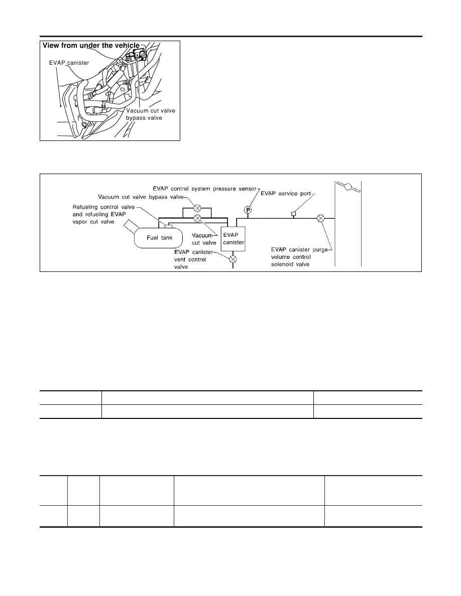
COMPONENT DESCRIPTION
NCEC0623S01
The vacuum cut valve and vacuum cut valve bypass valve are
installed in parallel on the EVAP purge line between the fuel tank
and the EVAP canister.
The vacuum cut valve prevents the intake manifold vacuum from
being applied to the fuel tank.
The vacuum cut valve bypass valve is a solenoid type valve and
generally remains closed. It opens only for on board diagnosis.
The vacuum cut valve bypass valve responds to signals from the
ECM. When the ECM sends an ON (ground) signal, the valve is
opened. The vacuum cut valve is then bypassed to apply intake
manifold vacuum to the fuel tank.
EVAPORATIVE EMISSION SYSTEM DIAGRAM
NCEC0623S02
SEF323U
CONSULT-II Reference Value in Data Monitor
Mode
NCEC0624
Specification data are reference values.
MONITOR ITEM
CONDITION
SPECIFICATION
VC/V BYPASS/V
I
Ignition switch: ON
OFF
ECM Terminals and Reference Value
NCEC0661
Specification data are reference values and are measured between each terminal and ground.
CAUTION:
Do not use ECM ground terminals when measuring input/output voltage. Doing so may result in dam-
age to the ECM’s transistor. Use a ground other than ECM terminals, such as the ground.
TER-
MINAL
NO.
WIRE
COLOR
ITEM
CONDITION
DATA (DC Voltage)
2
PU/R
Vacuum cut valve
bypass valve
[Ignition switch “ON”]
BATTERY VOLTAGE
(11 - 14V)
DTC P1490 VACUUM CUT VALVE BYPASS VALVE (CIRCUIT)
Description
EC-562
Нет комментариевНе стесняйтесь поделиться с нами вашим ценным мнением.
Текст