Infiniti G20 (P11). Manual — part 286
5
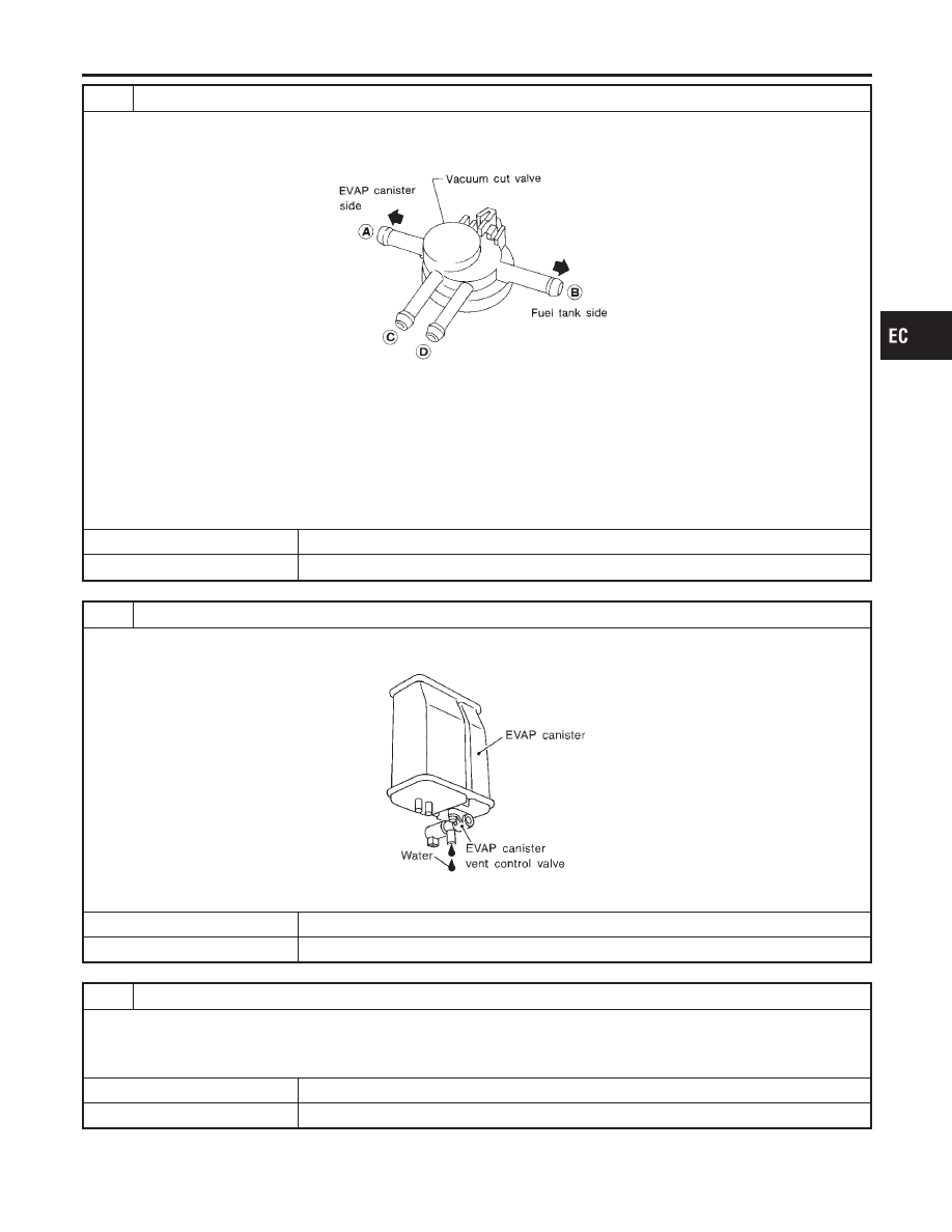
CHECK VACUUM CUT VALVE
1. Turn ignition switch OFF.
2. Remove vacuum cut valve.
3. Check vacuum cut valve as follows:
SEF379Q
a. Plug port C and D with fingers.
b. Apply vacuum to port A and check that there is no suction from port B.
c. Apply vacuum to port B and check that there is suction from port A.
d. Blow air in port B and check that there is a resistance to flow out of port A.
e. Open port C and D.
f. Blow air in port A check that air flows freely out of port C.
g. Blow air in port B check that air flows freely out of port D.
OK or NG
OK
©
GO TO 6.
NG
©
Replace vacuum cut valve.
6
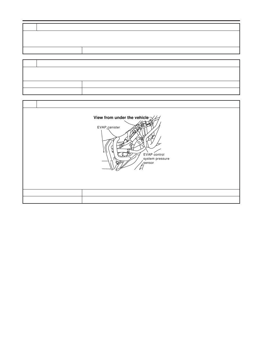
CHECK IF EVAP CANISTER SATURATED WITH WATER
1. Remove EVAP canister with EVAP canister vent control valve attached.
2. Check if water will drain from the EVAP canister.
SEF596U
Yes or No
Yes
©
GO TO 7.
No
©
GO TO 9.
7
CHECK EVAP CANISTER
Weigh the EVAP canister with the EVAP canister vent control valve attached.
The weight should be less than 1.8 kg (4.0 lb).
OK or NG
OK
©
GO TO 9.
NG
©
GO TO 8.
GI
MA
EM
LC
FE
CL
MT
AT
AX
SU
BR
ST
RS
BT
HA
SC
EL
IDX
DTC P1448 EVAPORATIVE EMISSION (EVAP) CANISTER VENT CONTROL
VALVE (OPEN)
Diagnostic Procedure (Cont’d)
EC-555
8
DETECT MALFUNCTIONING PART
Check the following.
I
EVAP canister for damage
I
EVAP hose between EVAP canister and water separator for clogging or poor connection
©
Repair hose or replace EVAP canister.
9
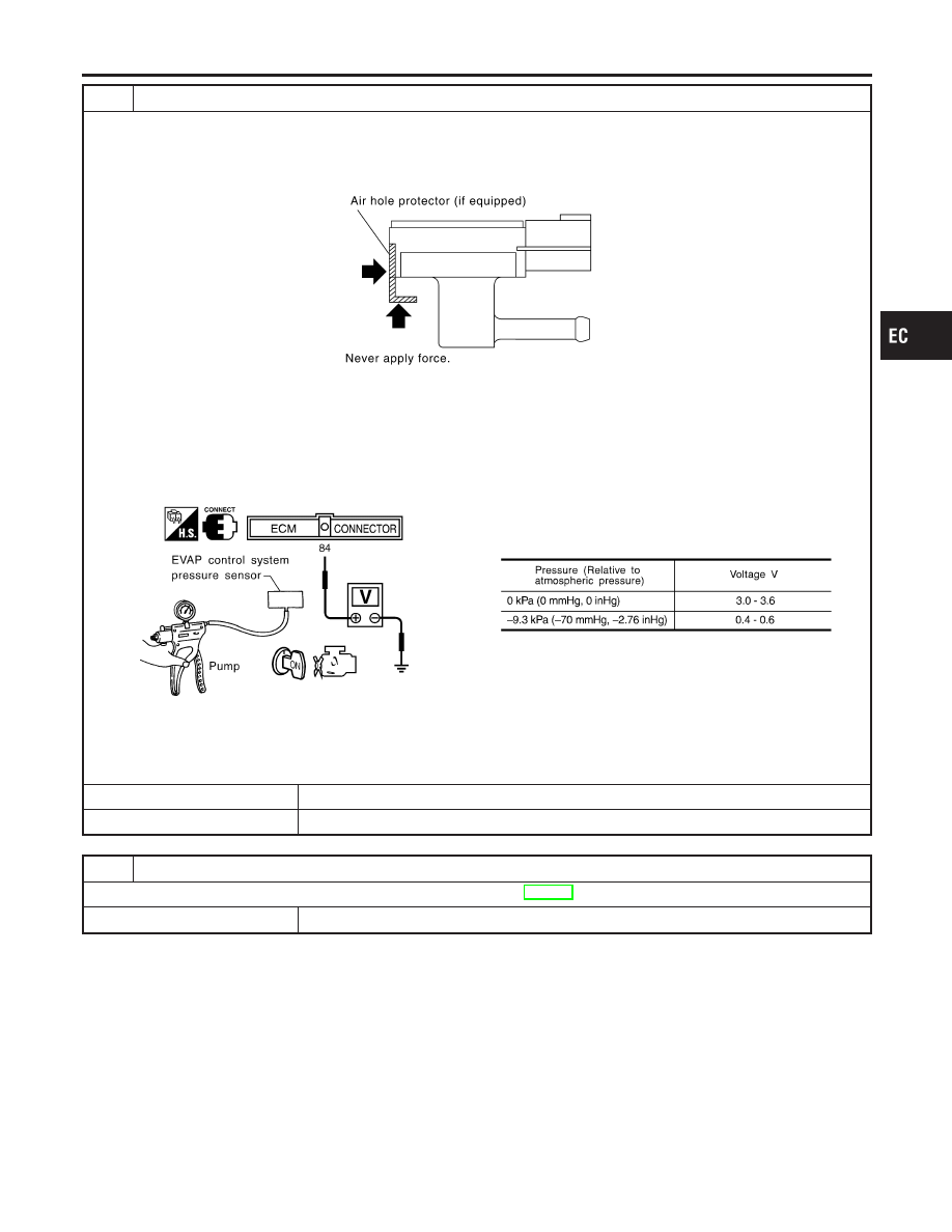
CHECK EVAP CONTROL SYSTEM PRESSURE SENSOR HOSE
Check disconnection or improper connection of hose connected to EVAP control system pressure sensor.
OK or NG
OK
©
GO TO 10.
NG
©
Repair it.
10
CHECK EVAP CONTROL SYSTEM PRESSURE SENSOR CONNECTOR
1. Disconnect EVAP control system pressure sensor harness connector.
SEF860X
2. Check connectors for water.
Water should not exist.
OK or NG
OK
©
GO TO 11.
NG
©
Replace EVAP control system pressure sensor.
DTC P1448 EVAPORATIVE EMISSION (EVAP) CANISTER VENT CONTROL
VALVE (OPEN)
Diagnostic Procedure (Cont’d)
EC-556
11
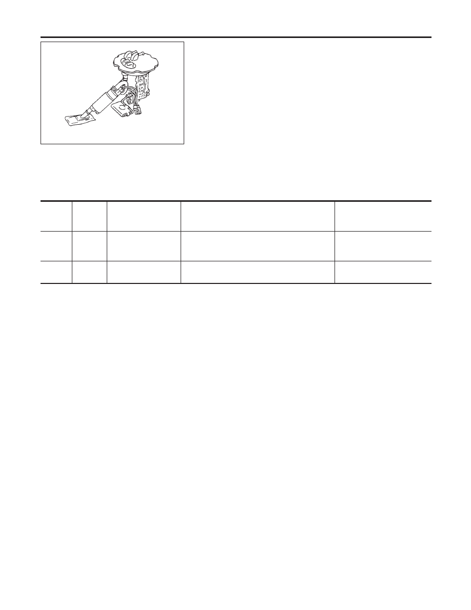
CHECK EVAP CONTROL SYSTEM PRESSURE SENSOR
1. Remove EVAP control system pressure sensor with its harness connector connected.
CAUTION:
I
Never apply force to the air hole protector of the sensor if equipped.
SEF799W
2. Remove hose from EVAP control system pressure sensor.
3. Turn ignition switch “ON”.
4. Use pump to apply vacuum and pressure to EVAP control system pressure sensor as shown in figure.
CAUTION:
I
Always calibrate the vacuum pump gauge when using it.
I
Do not apply below −20 kPa (−150 mmHg, −5.91 inHg) or over 20 kPa (150 mmHg, 5.91 inHg) of pressure.
5. Check input voltage between ECM terminal 84 and ground.
SEF342X
CAUTION:
I
Discard and EVAP control system pressure sensor which has been dropped from a height of more than 0.5 m
(19.7 in) onto a hard surface such as a concrete floor; use a new one.
OK or NG
OK
©
GO TO 12.
NG
©
Replace EVAP control system pressure sensor.
12
CHECK INTERMITTENT INCIDENT
Refer to “TROUBLE DIAGNOSIS FOR INTERMITTENT INCIDENT”, EC-146.
©
INSPECTION END
GI
MA
EM
LC
FE
CL
MT
AT
AX
SU
BR
ST
RS
BT
HA
SC
EL
IDX
DTC P1448 EVAPORATIVE EMISSION (EVAP) CANISTER VENT CONTROL
VALVE (OPEN)
Diagnostic Procedure (Cont’d)
EC-557
AEC801
Component Description
NCEC0617
The fuel level sensor is mounted in the fuel level sensor unit. The
sensor detects a fuel level in the fuel tank and transmits a signal
to the ECM.
It consists of two parts, one is mechanical float and the other side
is variable resistor. Fuel level sensor output voltage changes
depending on the movement of the fuel mechanical float.
ECM Terminals and Reference Value
NCEC0660
Specification data are reference values and are measured between each terminal and ground.
CAUTION:
Do not use ECM ground terminals when measuring input/output voltage. Doing so may result in dam-
age to the ECM’s transistor. Use a ground other than ECM terminals, such as the ground.
TERMI-
NAL
NO.
WIRE
COLOR
ITEM
CONDITION
DATA (DC Voltage)
83
G/R
Fuel level sensor
[Ignition switch “ON”]
Approximately 0 - 4.8V
Output voltage varies with fuel
level.
90
B
Fuel level sensor
ground
[Engine is running]
Approximately 0V
On Board Diagnostic Logic
NCEC0618
ECM receives two signals from the fuel level sensor.
One is fuel level sensor power supply circuit, and the other is fuel
level sensor ground circuit.
This diagnosis indicates the latter to detect open circuit malfunc-
tion. Malfunction is detected when a high voltage from the sensor
is sent to ECM.
Possible Cause
NCEC0619
I
Fuel level sensor circuit
(The fuel level sensor circuit is open or shorted.)
DTC P1464 FUEL LEVEL SENSOR CIRCUIT (GROUND SIGNAL)
Component Description
EC-558
Нет комментариевНе стесняйтесь поделиться с нами вашим ценным мнением.
Текст