Infiniti G20 (P11). Manual — part 81
Control Valve Upper Body
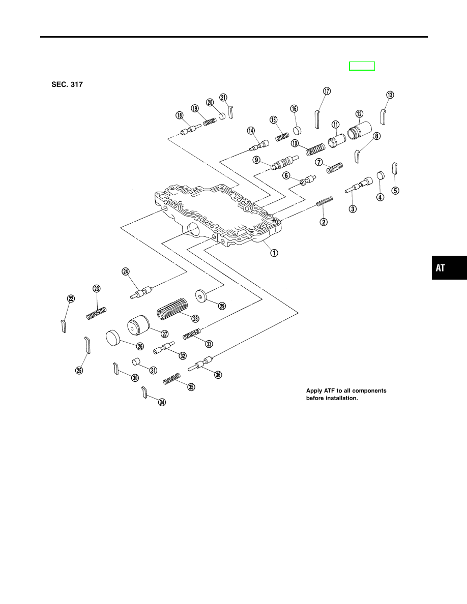
COMPONENTS
=NCAT0133
Numbers preceding valve springs correspond with those shown in SDS table on page AT-390.
SAT863J
1.
Control valve upper body
2.
Return spring
3.
Overrun clutch reducing valve
4.
Plug
5.
Retainer plate
6.
Torque converter relief valve
7.
Return spring
8.
Retainer plate
9.
Torque converter clutch control
valve
10. Return spring
11. Plug
12. Sleeve
13. Retainer plate
14. 1-2 accumulator valve
15. Return spring
16. Plug
17. Retainer plate
18. Cooler check valve
19. Return spring
20. Plug
21. Retainer plate
22. Retainer plate
23. Return spring
24. Pilot valve
25. Retainer plate
26. Plug
27. 1-2 accumulator piston
28. Return spring
29. 1-2 accumulator retainer plate
30. Retainer plate
31. Plug
32. 1st reducing valve
33. Return spring
34. Retainer plate
35. Return spring
36. 3-2 timing valve
GI
MA
EM
LC
EC
FE
CL
MT
AX
SU
BR
ST
RS
BT
HA
SC
EL
IDX
REPAIR FOR COMPONENT PARTS
Control Valve Upper Body
AT-321
SAT321G
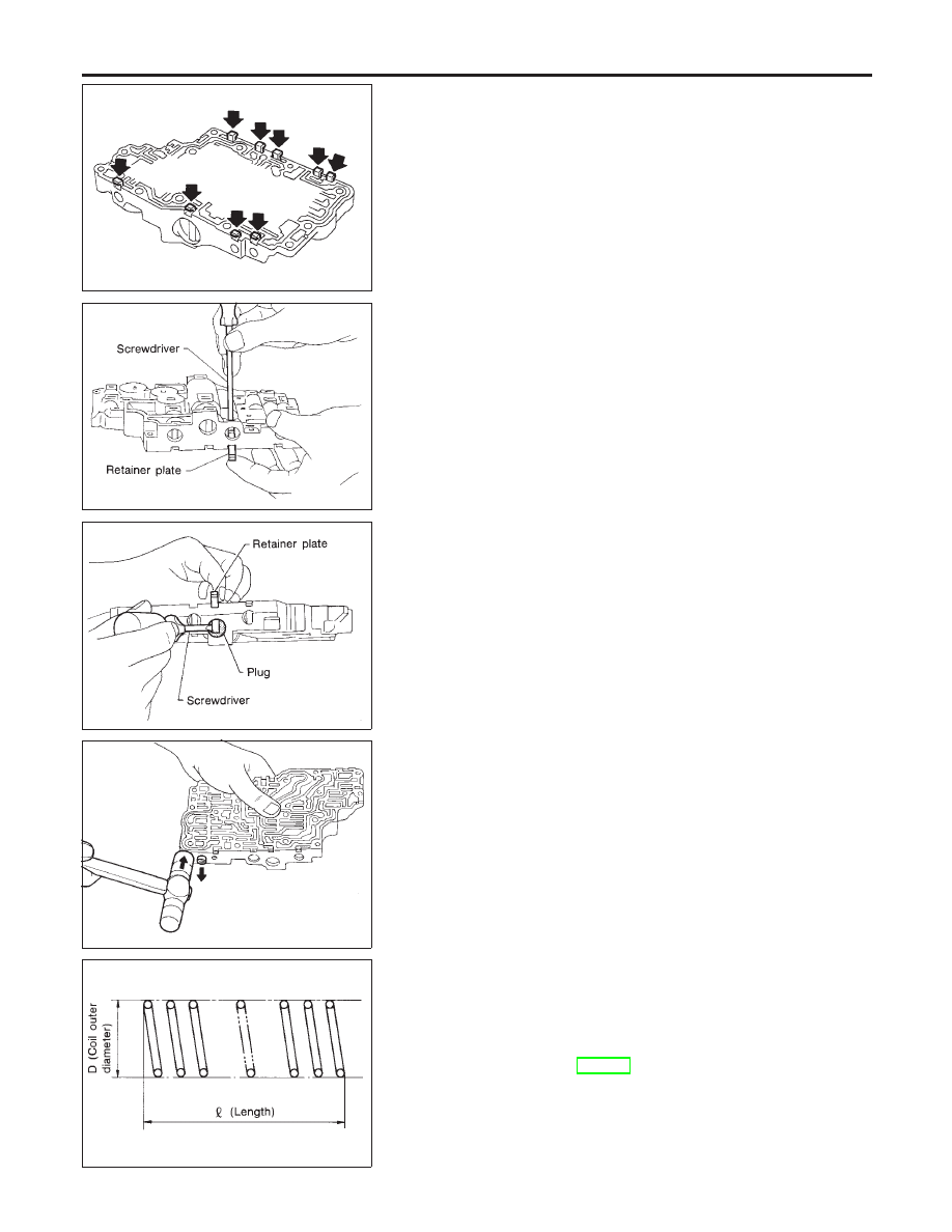
DISASSEMBLY
NCAT0134
1.
Remove valves at retainer plates.
I
Do not use a magnetic “hand”.
SAT135D
a.
Use a screwdriver to remove retainer plates.
SAT136D
b.
Remove retainer plates while holding spring, plugs or sleeves.
I
Remove plugs slowly to prevent internal parts from jump-
ing out.
SAT137D
c.
Place mating surface of valve body face down, and remove
internal parts.
I
If a valve is hard to remove, place valve body face down
and lightly tap it with a soft hammer.
I
Be careful not to drop or damage valves and sleeves.
SAT138D
INSPECTION
NCAT0135
Valve Spring
NCAT0135S01
I
Measure free length and outer diameter of each valve spring.
Also check for damage or deformation.
Inspection standard:
Refer to SDS, AT-390.
I
Replace valve springs if deformed or fatigued.
Control Valves
NCAT0135S02
I
Check sliding surfaces of valves, sleeves and plugs.
REPAIR FOR COMPONENT PARTS
Control Valve Upper Body (Cont’d)
AT-322
SAT139D
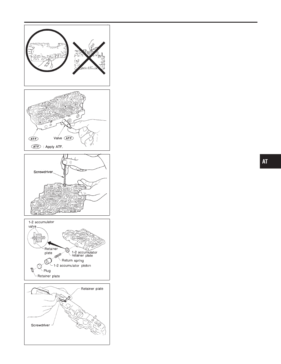
ASSEMBLY
NCAT0136
I
Lay control valve body down when installing valves. Do
not stand the control valve body upright.
SAT140DA
1.
Lubricate the control valve body and all valves with ATF. Install
control valves by sliding them carefully into their bores.
I
Be careful not to scratch or damage valve body.
SAT141D
I
Wrap a small screwdriver with vinyl tape and use it to insert the
valves into their proper positions.
SAT142D
1-2 Accumulator Valve
NCAT0136S01
I
Install 1-2 accumulator valve. Align 1-2 accumulator retainer
plate from opposite side of control valve body.
I
Install return spring, 1-2 accumulator piston and plug.
SAT143D
1.
Install retainer plates.
I
Install retainer plate while pushing plug or return spring.
GI
MA
EM
LC
EC
FE
CL
MT
AX
SU
BR
ST
RS
BT
HA
SC
EL
IDX
REPAIR FOR COMPONENT PARTS
Control Valve Upper Body (Cont’d)
AT-323
SAT086F
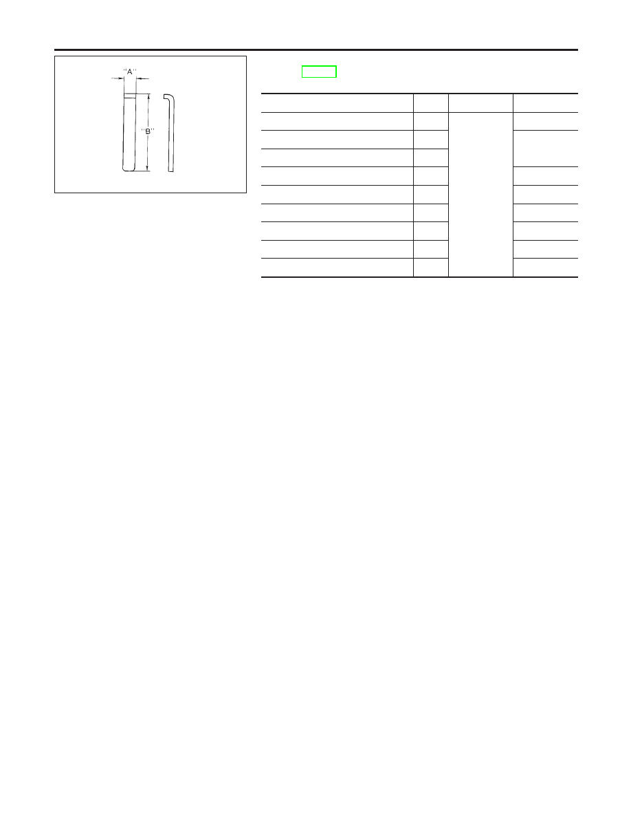
Retainer Plate (for control valve upper body)
NCAT0136S02
Refer to AT-321.
Unit: mm (in)
Name of valve and piston
No.
Length A
Length B
Pilot valve
22
6.0 (0.236)
21.5 (0.846)
1-2 accumulator valve
17
38.5 (1.516)
1-2 accumulator piston
25
1st reducing valve
30
21.5 (0.846)
Overrun clutch reducing valve
5
24.0 (0.945)
Torque converter relief valve
8
21.5 (0.846)
Torque converter clutch control valve
13
28.0 (1.102)
3-2 timing valve
34
21.5 (0.846)
Cooler check valve
21
24.0 (0.945)
I
Install proper retainer plates.
REPAIR FOR COMPONENT PARTS
Control Valve Upper Body (Cont’d)
AT-324
Нет комментариевНе стесняйтесь поделиться с нами вашим ценным мнением.
Текст