Infiniti G20 (P11). Manual — part 237
Possible Cause
NCEC0523
I
Harness or connectors
(EGR volume control valve circuit is open or shorted.)
I
EGR volume control valve
SEF174Y
DTC Confirmation Procedure
NCEC0524
NOTE:
If “DTC Confirmation Procedure” has been previously conducted,
always turn ignition switch “OFF” and wait at least 10 seconds
before conducting the next test.
TESTING CONDITION:
Before performing the following procedure, confirm that bat-
tery voltage is more than 10V at idle.
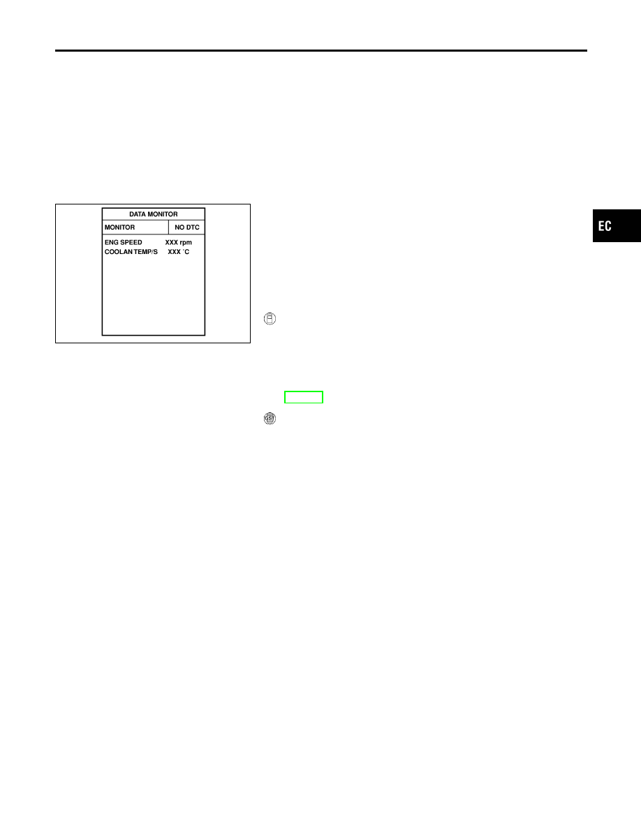
WITH CONSULT-II
NCEC0524S01
1)
Turn ignition switch “ON” and select “DATA MONITOR” mode
with CONSULT-II.
2)
Start engine and warm it up to normal operating temperature.
3)
Rev engine from idle to 2,000 rpm 10 times.
4)
If 1st trip DTC is detected, go to “Diagnostic Procedure”,
EC-361.
WITH GST
NCEC0524S02
Follow the procedure “With CONSULT-II” above.
GI
MA
EM
LC
FE
CL
MT
AT
AX
SU
BR
ST
RS
BT
HA
SC
EL
IDX
DTC P0403 EGR VOLUME CONTROL VALVE (CIRCUIT)
Possible Cause
EC-359
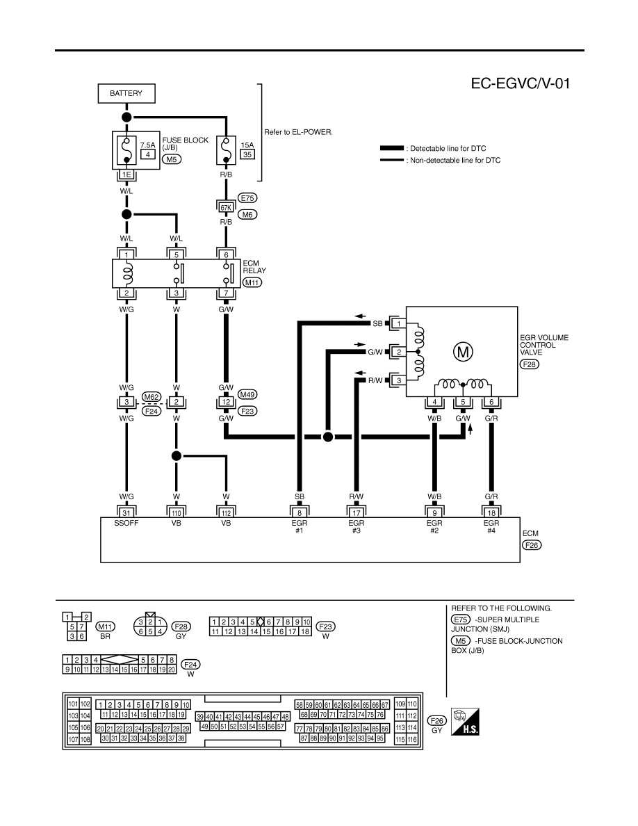
Wiring Diagram
=NCEC0525
TEC835
DTC P0403 EGR VOLUME CONTROL VALVE (CIRCUIT)
Wiring Diagram
EC-360
Diagnostic Procedure
NCEC0526
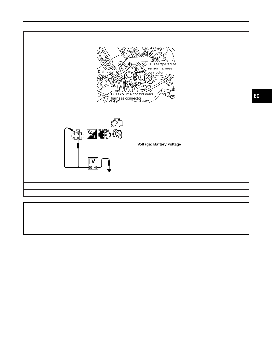
1
CHECK EGR VOLUME CONTROL VALVE POWER SUPPLY CIRCUIT
1. Disconnect EGR volume control valve harness connector.
SEF849X
2. Turn ignition switch “ON”.
3. Check voltage between EGR volume control valve terminals 2, 5 and ground with CONSULT-II or tester.
SEF327X
OK or NG
OK
©
GO TO 3.
NG
©
GO TO 2.
2
DETECT MALFUNCTIONING PART
Check the following.
I
Harness connectors F23, M49
I
Harness for open or short between ECM relay and EGR volume control valve
©
Repair harness or connectors.
GI
MA
EM
LC
FE
CL
MT
AT
AX
SU
BR
ST
RS
BT
HA
SC
EL
IDX
DTC P0403 EGR VOLUME CONTROL VALVE (CIRCUIT)
Diagnostic Procedure
EC-361
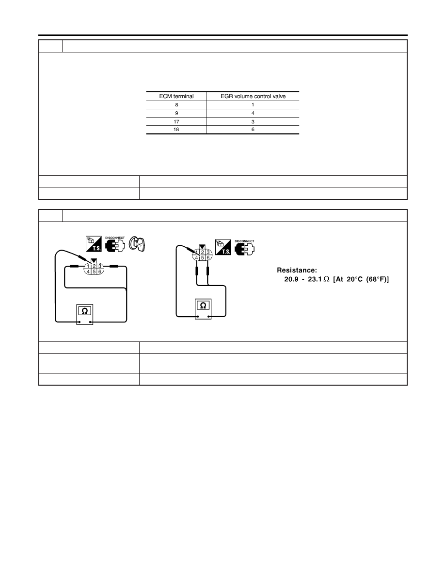
3
CHECK EGR VOLUME CONTROL VALVE OUTPUT SIGNAL CIRCUIT FOR OPEN AND SHORT
1. Turn ignition switch “OFF”.
2. disconnect ECM harness connector.
3. Check harness continuity between ECM terminals and EGR volume control valve terminals as follows.
Refer to Wiring Diagram.
MTBL0389
Continuity should exist.
4. Also check harness for short to ground and short to power.
OK or NG
OK
©
GO TO 4.
NG
©
Repair open circuit or short to ground or short to power in harness or connectors.
4
CHECK EGR VOLUME CONTROL VALVE-I
Check resistance between EGR volume control valve terminal 2 and terminals 1, 3, terminal 5 and terminals 4, 6.
SEF588X
OK or NG
OK (With CONSULT-II)
©
GO TO 5.
OK (Without CONSULT-
II)
©
GO TO 6.
NG
©
Replace EGR volume control valve.
DTC P0403 EGR VOLUME CONTROL VALVE (CIRCUIT)
Diagnostic Procedure (Cont’d)
EC-362
Нет комментариевНе стесняйтесь поделиться с нами вашим ценным мнением.
Текст