Infiniti G20 (P11). Manual — part 235
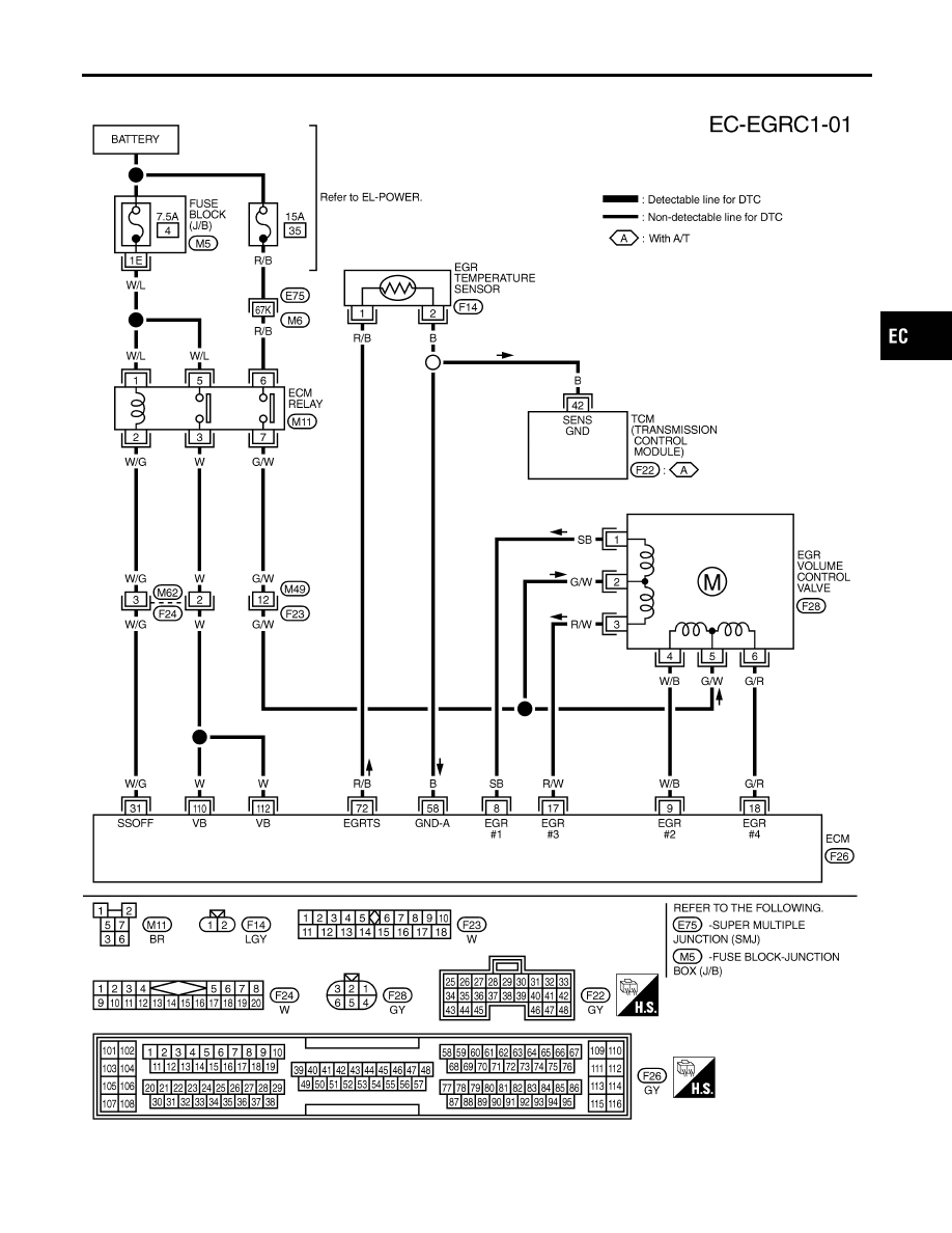
Wiring Diagram
NCEC0518
TEC836
GI
MA
EM
LC
FE
CL
MT
AT
AX
SU
BR
ST
RS
BT
HA
SC
EL
IDX
DTC P0400 EGR FUNCTION (CLOSE)
Wiring Diagram
EC-351
Diagnostic Procedure
NCEC0519
1
CHECK EXHAUST SYSTEM
1. Start engine.
2. Check exhaust pipes and muffler for leaks.
SEF099P
OK or NG
OK
©
GO TO 2.
NG
©
Repair or replace exhaust system.
2
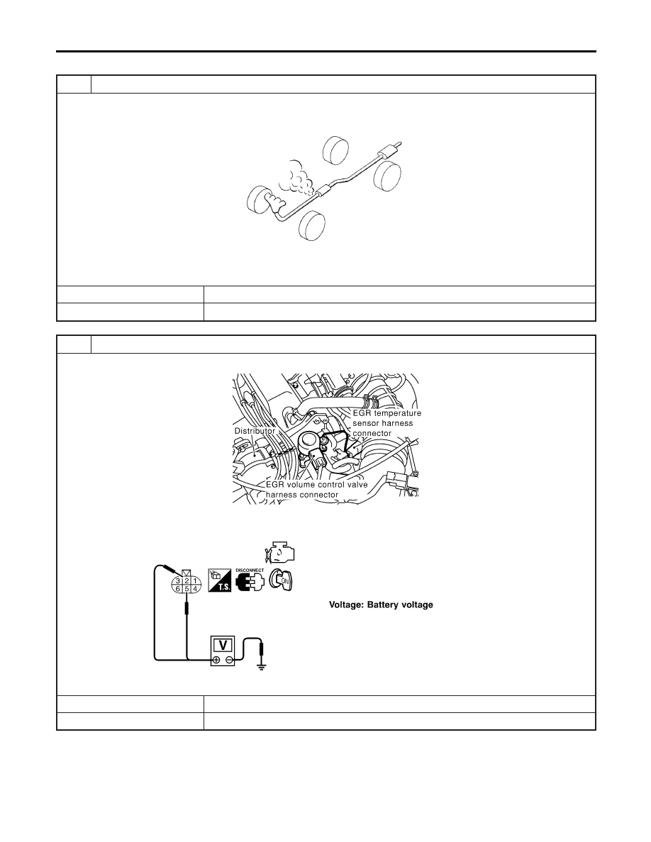
CHECK EGR VOLUME CONTROL VALVE POWER SUPPLY CIRCUIT
1. Disconnect EGR volume control vale harness connector.
SEF849X
2. Turn ignition switch “ON”.
3. Check voltage between EGR volume control valve terminals 2, 5 and ground with CONSULT-II or tester.
SEF327X
OK or NG
OK
©
GO TO 4.
NG
©
GO TO 3.
DTC P0400 EGR FUNCTION (CLOSE)
Diagnostic Procedure
EC-352
3
DETECT MALFUNCTIONING PART
Check the following.
I
Harness connectors F23, M49
I
Harness for open or short between ECM relay and EGR volume control valve
©
Repair harness or connectors.
4
CHECK EGR VOLUME CONTROL VALVE OUTPUT SIGNAL CIRCUIT FOR OPEN AND SHORT
1. Turn ignition switch “OFF”.
2. Disconnect ECM harness connector.
3. Check harness continuity between ECM terminals and EGR volume control valve terminals as follows.
Refer to Wiring Diagram.
MTBL0389
Continuity should exist.
4. Also check harness for short to ground and short to power.
OK or NG
OK
©
GO TO 5.
NG
©
Repair open circuit or short to ground or short to power in harness or connectors.
5
CHECK EGR PASSAGE
Check EGR passage for clogging and cracks.
OK or NG
OK
©
GO TO 6.
NG
©
Repair or replace EGR passage.
GI
MA
EM
LC
FE
CL
MT
AT
AX
SU
BR
ST
RS
BT
HA
SC
EL
IDX
DTC P0400 EGR FUNCTION (CLOSE)
Diagnostic Procedure (Cont’d)
EC-353
6
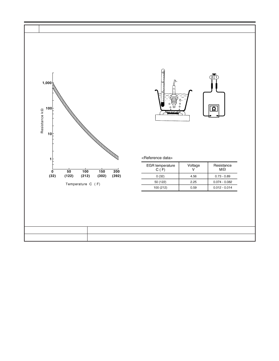
CHECK EGR TEMPERATURE SENSOR AND CIRCUIT
1. Remove EGR temperature sensor.
2. Check resistance between EGR temperature sensor terminals 1 and 2 under the following conditions.
SEF919Z
OK or NG
OK
©
GO TO 7.
NG
©
Replace EGR temperature sensor.
DTC P0400 EGR FUNCTION (CLOSE)
Diagnostic Procedure (Cont’d)
EC-354
Нет комментариевНе стесняйтесь поделиться с нами вашим ценным мнением.
Текст