Infiniti G20 (P11). Manual — part 70
8
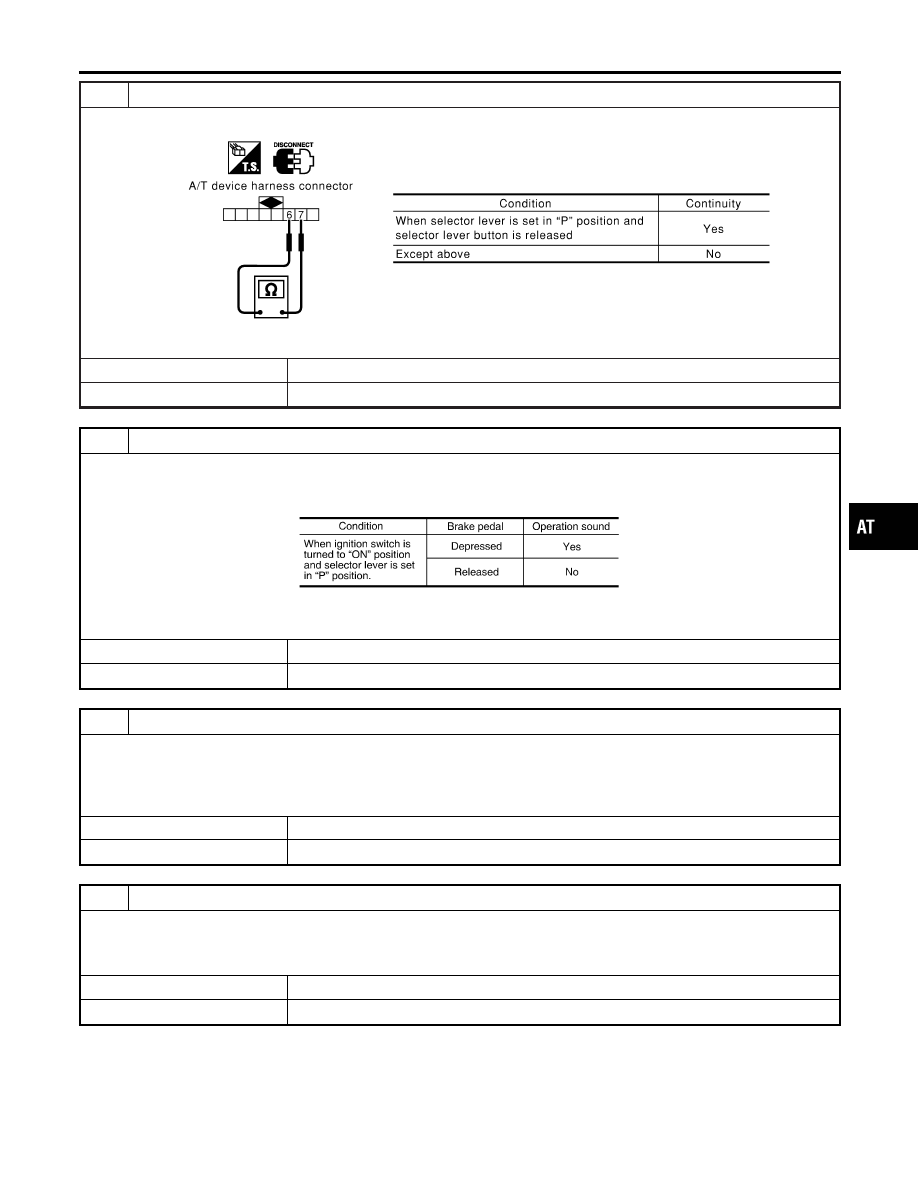
CHECK PARK POSITION SWITCH AND RELAY CIRCUIT (COIL SIDE)
I
Check continuity between A/T device harness connector M48 terminals 6 (B) and 7 (R/G).
SAT665K
OK or NG
OK
©
GO TO 9.
NG
©
Replace park position switch or relay.
9
CHECK SHIFT LOCK SOLENOID AND RELAY CIRCUIT (POINT SIDE)
1. Connect A/T device harness connector.
2. Turn ignition switch to “ON” position.
3. Check operation sound.
MTBL1313
OK or NG
OK
©
GO TO 10.
NG
©
Replace shift lock solenoid or relay.
10
CHECK SHIFT LOCK OPERATION
1. Reconnect shift lock harness connector.
2. Turn ignition switch from OFF to ON position. (Do not start engine.)
3. Recheck shift lock operation.
OK or NG
OK
©
INSPECTION END
NG
©
GO TO 11.
11
CHECK A/T DEVICE INSPECTION
1. Perform A/T device input/output signal inspection test.
2. If NG, recheck harness connector connection.
OK or NG
OK
©
INSPECTION END
NG
©
Repair or replace damaged parts.
GI
MA
EM
LC
EC
FE
CL
MT
AX
SU
BR
ST
RS
BT
HA
SC
EL
IDX
A/T SHIFT LOCK SYSTEM
Diagnostic Procedure (Cont’d)
AT-277
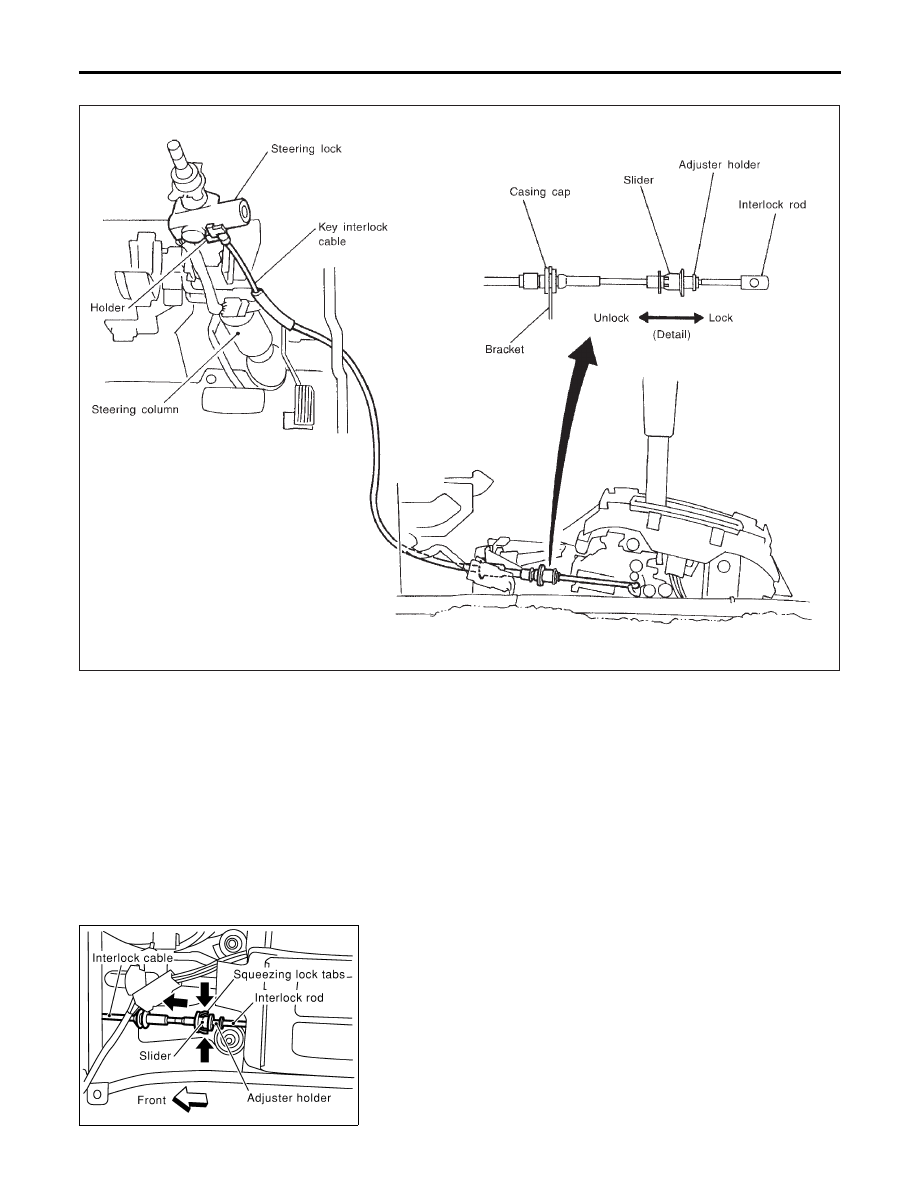
Components
NCAT0107
SAT411J
CAUTION:
I
Install key interlock cable in such a way that it will not be
damaged by sharp bends, twists or interference with adja-
cent parts.
I
After installing key interlock cable to control device, make
sure that casing cap and bracket are firmly secured in
their positions.
SAT853J
Removal
NCAT0108
1.
Unlock slider by squeezing lock tabs on slider from adjuster
holder and remove interlock rod from cable.
KEY INTERLOCK CABLE
Components
AT-278
SAT854J
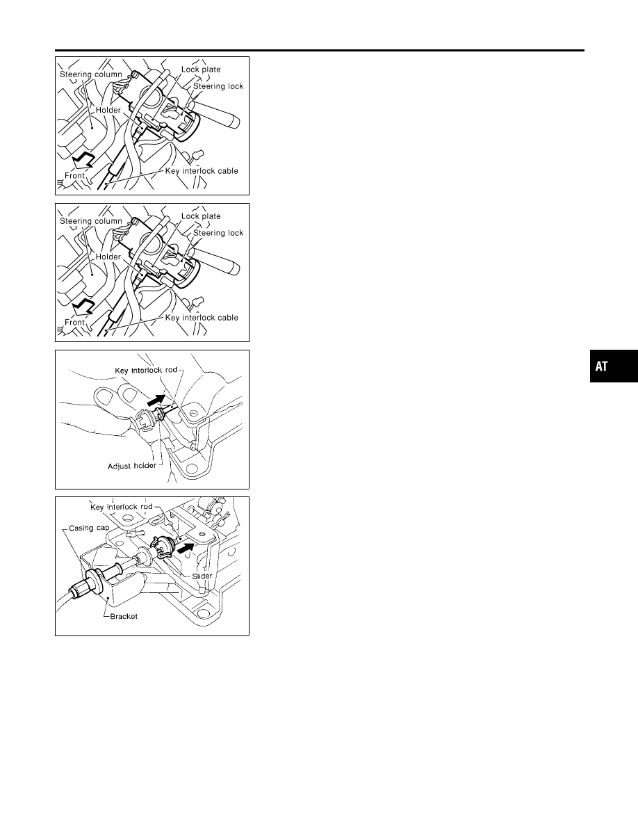
2.
Remove lock plate from steering lock assembly and remove
key interlock cable.
SAT854J
Installation
NCAT0109
1.
Turn ignition key to lock position.
2.
Set A/T selector lever to P position.
3.
Set key interlock cable to steering lock assembly and install
lock plate.
4.
Clamp cable to steering column and fix to control cable with
band.
SAT804E
5.
Insert interlock rod into adjuster holder.
SAT805E
6.
Install casing cap to bracket.
7.
Move slider in order to fix adjuster holder to interlock rod.
GI
MA
EM
LC
EC
FE
CL
MT
AX
SU
BR
ST
RS
BT
HA
SC
EL
IDX
KEY INTERLOCK CABLE
Removal (Cont’d)
AT-279
SAT992C
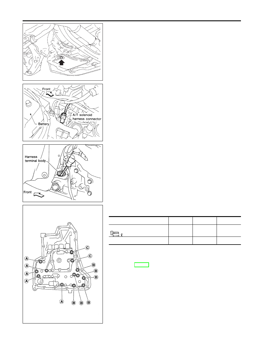
Control Valve Assembly and Accumulators
NCAT0110
REMOVAL
NCAT0110S01
1.
Drain ATF from transaxle.
2.
Remove oil pan and gasket.
AAT264A
3.
Disconnect A/T solenoid harness connector.
AAT265A
4.
Remove stopper ring from A/T solenoid harness terminal body.
5.
Remove A/T solenoid harness by pushing terminal body into
transmission case.
AAT260A
6.
Remove control valve assembly by removing fixing bolts.
Bolt length, number and location:
Bolt symbol
A
B
C
Bolt length “
”
40.0 mm
(1.575 in)
33.0 mm
(1.299 in)
43.5 mm
(1.713 in)
Number of bolts
5
6
2
I
Be careful not to drop manual valve and servo release
accumulator return springs.
7.
Disassemble and inspect control valve assembly if necessary.
Refer to AT-291.
ON-VEHICLE SERVICE
Control Valve Assembly and Accumulators
AT-280
Нет комментариевНе стесняйтесь поделиться с нами вашим ценным мнением.
Текст