Infiniti G20 (P11). Manual — part 68
6
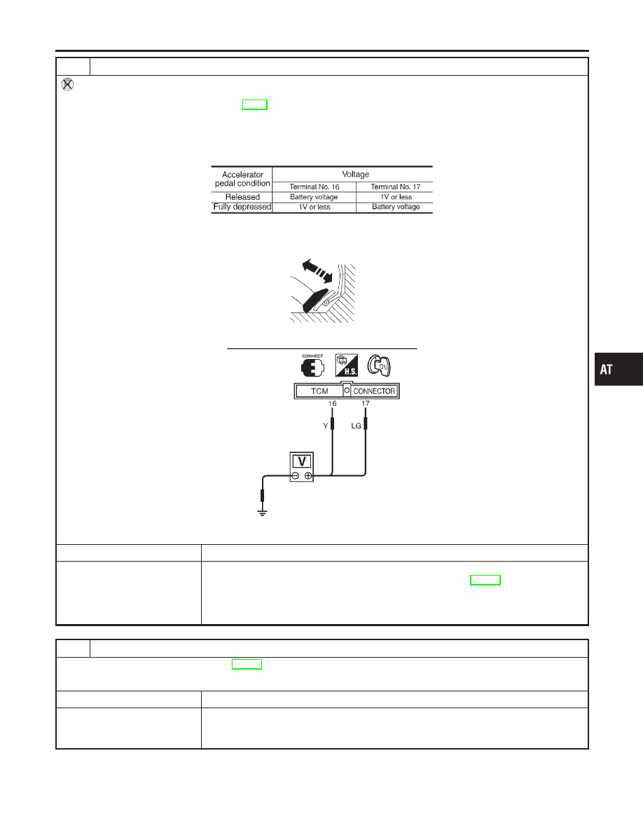
CHECK THROTTLE POSITION SWITCH CIRCUIT (Without CONSULT-II)
Without CONSULT-II
1. Apply vacuum to the throttle opener, then check the following. Refer from step 1 to 5 of “Preparation”, “TCM SELF-DI-
AGNOSTIC PROCEDURE (No Tools)”, AT-49.
2. Turn ignition switch to “ON” position.
(Do not start engine.)
3. Check voltage between TCM terminals 16, 17 and ground while depressing, and releasing accelerator pedal slowly.
(After warming up engine)
MTBL0137
SAT454J
OK or NG
OK
©
GO TO 7.
NG
©
Check the following items:
I
Throttle position switch — Refer to “Component Inspection”, AT-270.
I
Harness for short or open between ignition switch and throttle position switch (Main
harness)
I
Harness for short or open between throttle position switch and TCM (Main harness)
7
CHECK DTC
Perform “DIAGNOSTIC PROCEDURE”, AT-264.
OK or NG
OK
©
INSPECTION END
NG
©
I
Perform TCM input/output signal inspection.
I
If NG, recheck TCM pin terminals for damage or loose connection with harness con-
nector.
GI
MA
EM
LC
EC
FE
CL
MT
AX
SU
BR
ST
RS
BT
HA
SC
EL
IDX
TROUBLE DIAGNOSES FOR SYMPTOMS
21. TCM Self-diagnosis Does Not Activate (PNP, Overdrive Control and Throttle Position Switches Circuit Checks) (Cont’d)
AT-269
SAT472J
COMPONENT INSPECTION
NCAT0101S03
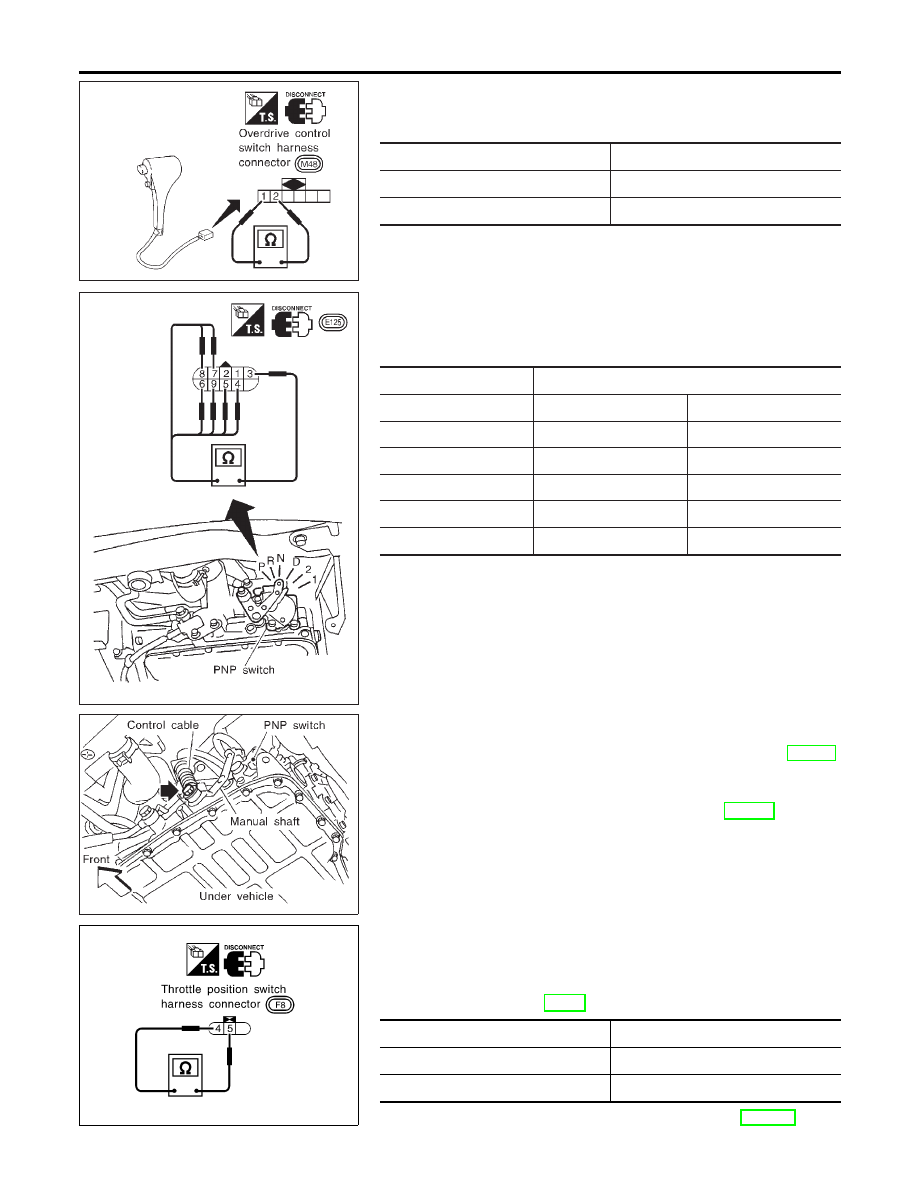
Overdrive Control Switch
NCAT0101S0301
I
Check continuity between two terminals.
Switch position
Continuity
ON
No
OFF
Yes
SAT402J
PNP Switch
NCAT0101S0302
1.
Check continuity between terminals 1 and 3 and between ter-
minals 2 and 4, 5, 6, 7, 8, 9 while moving manual shaft through
each position.
Lever position
Terminal No.
P
3 — 7
1 — 2
R
3 — 8
N
3 — 9
1 — 2
D
3 — 6
2
3 — 5
1
3 — 4
SAT089JA
2.
If NG, check again with manual control cable disconnected
from manual shaft of A/T assembly. Refer to step 1.
3.
If OK on step 2, adjust manual control cable. Refer to AT-281.
4.
If NG on step 2, remove PNP switch from A/T and check con-
tinuity of PNP switch terminals. Refer to step 1.
5.
If OK on step 4, adjust PNP switch. Refer to AT-281.
6.
If NG on step 4, replace PNP switch.
SAT851J
Throttle Position Switch
NCAT0101S0303
Closed throttle position switch (idle position)
I
Check continuity between terminals 4 and 5.
Refer to “Preparation”, “TCM SELF-DIAGNOSTIC PROCE-
DURE (No Tools)”, AT-49.
Accelerator pedal condition
Continuity
Released
Yes
Depressed
No
I
To adjust closed throttle position switch, refer to EC-445, “DTC
TROUBLE DIAGNOSES FOR SYMPTOMS
21. TCM Self-diagnosis Does Not Activate (PNP, Overdrive Control and Throttle Position Switches Circuit Checks) (Cont’d)
AT-270
P0510 CLOSED THROTTLE POSITION SWITCH”.
SAT852J
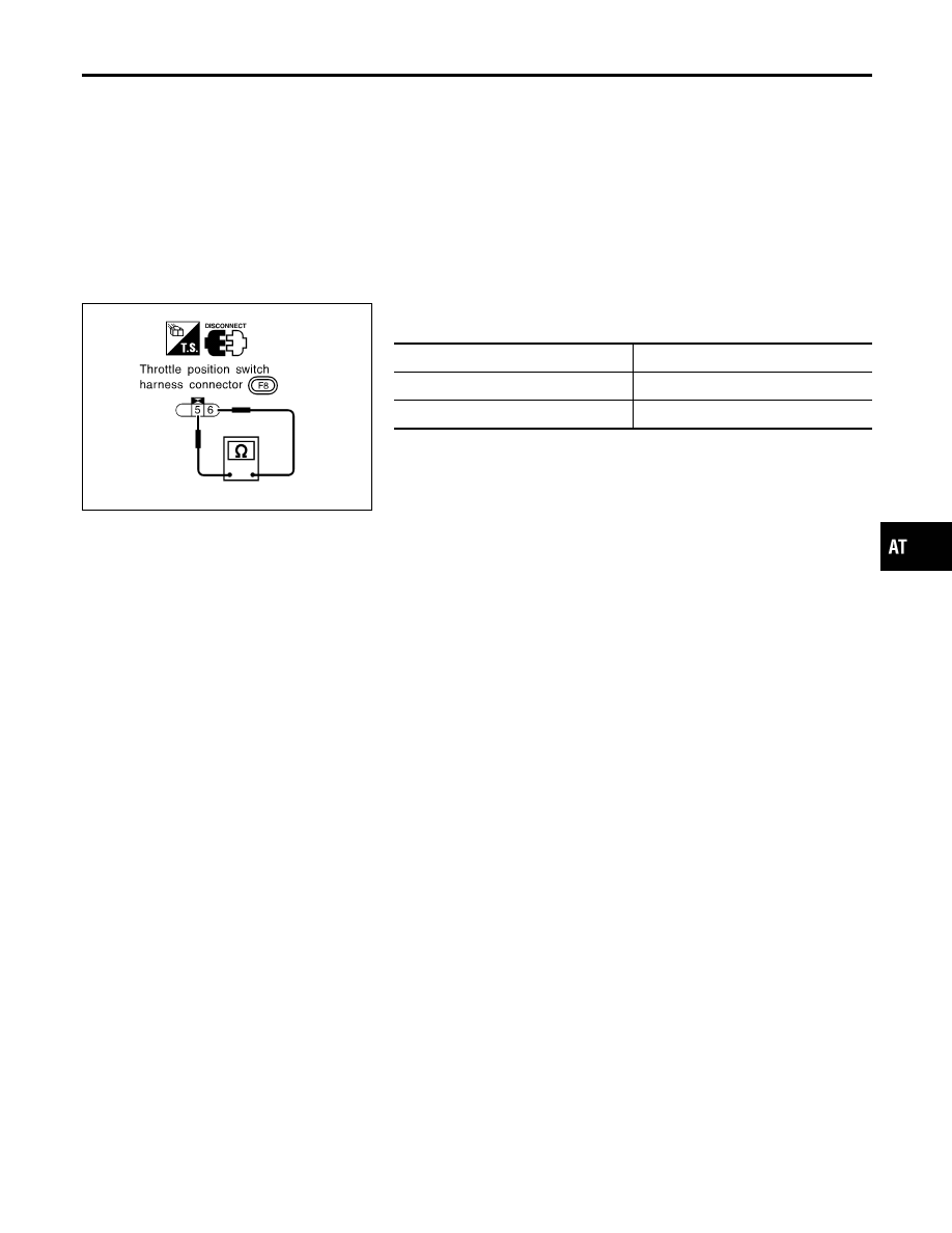
Wide open throttle position switch
I
Check continuity between terminals 5 and 6.
Accelerator pedal condition
Continuity
Released
No
Depressed
Yes
GI
MA
EM
LC
EC
FE
CL
MT
AX
SU
BR
ST
RS
BT
HA
SC
EL
IDX
TROUBLE DIAGNOSES FOR SYMPTOMS
21. TCM Self-diagnosis Does Not Activate (PNP, Overdrive Control and Throttle Position Switches Circuit Checks) (Cont’d)
AT-271
Description
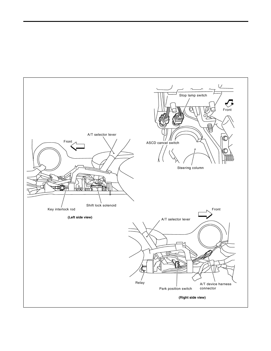
NCAT0102
I
The mechanical key interlock mechanism also operates as a shift lock:
With the key switch turned to ON, the selector lever cannot be shifted from “P” (parking) to any other
position unless the brake pedal is depressed.
With the key removed, the selector lever cannot be shifted from “P” to any other position.
The key cannot be removed unless the selector lever is placed in “P”.
I
The shift lock and key interlock mechanisms are controlled by the ON-OFF operation of the shift lock
solenoid and by the operation of the rotator and slider located inside the key cylinder.
Shift Lock System Electrical Parts Location
NCAT0103
SAT862J
A/T SHIFT LOCK SYSTEM
Description
AT-272
Нет комментариевНе стесняйтесь поделиться с нами вашим ценным мнением.
Текст