Infiniti G20 (P11). Manual — part 223
10
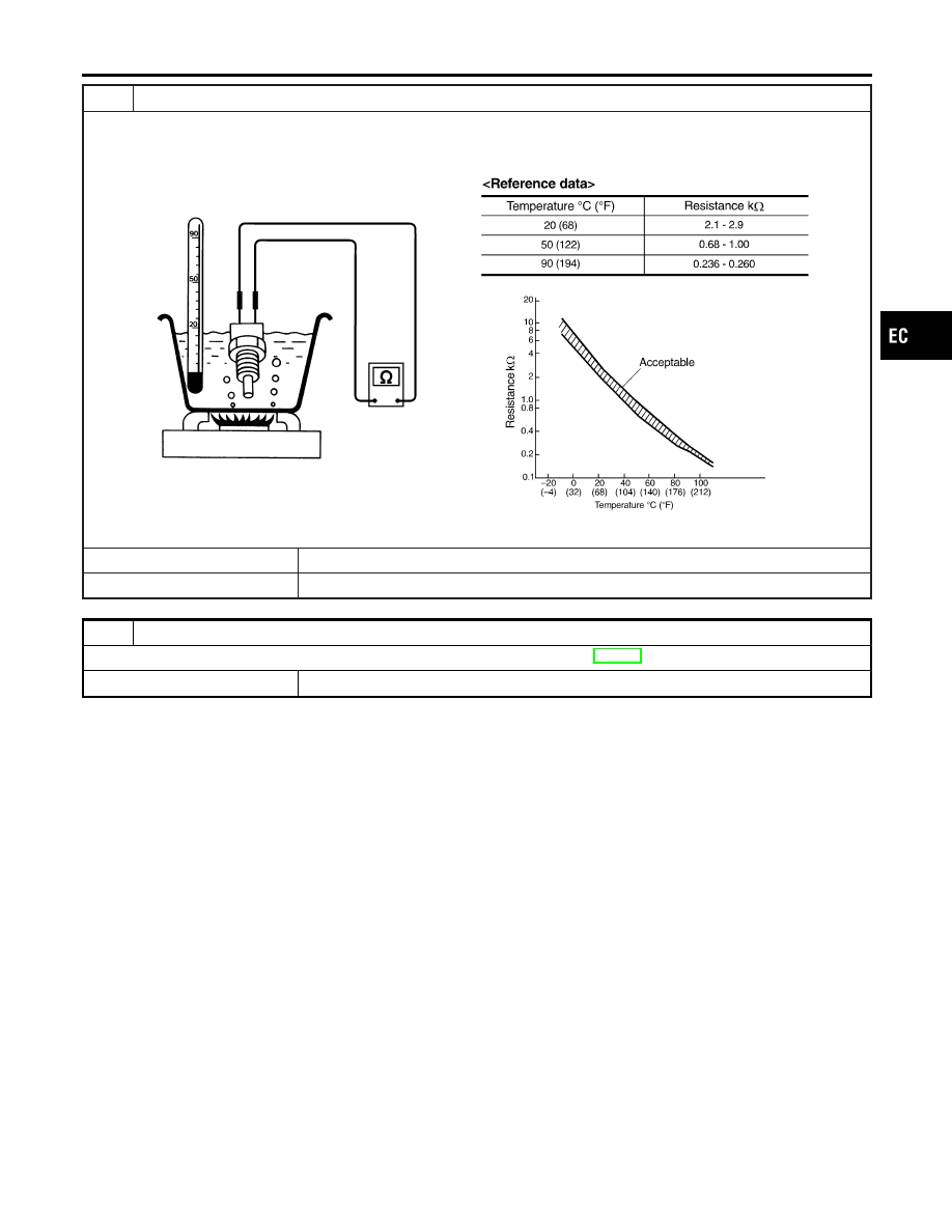
CHECK ENGINE COOLANT TEMPERATURE SENSOR
1. Remove engine coolant temperature sensor.
2. Check resistance between engine coolant temperature sensor terminals 1 and 2 as shown in the figure.
SEF304X
OK or NG
OK
©
GO TO 11.
NG
©
Replace engine coolant temperature sensor.
11
CHECK MAIN 12 CAUSES
If the cause cannot be isolated, go to “MAIN 12 CAUSES OF OVERHEATING”, EC-321.
©
INSPECTION END
GI
MA
EM
LC
FE
CL
MT
AT
AX
SU
BR
ST
RS
BT
HA
SC
EL
IDX
DTC P0217 COOLANT OVERTEMPERATURE ENRICHMENT PROTECTION
Diagnostic Procedure (A/T Models) (Cont’d)
EC-303
PROCEDURE A
=NCEC0511S01
1
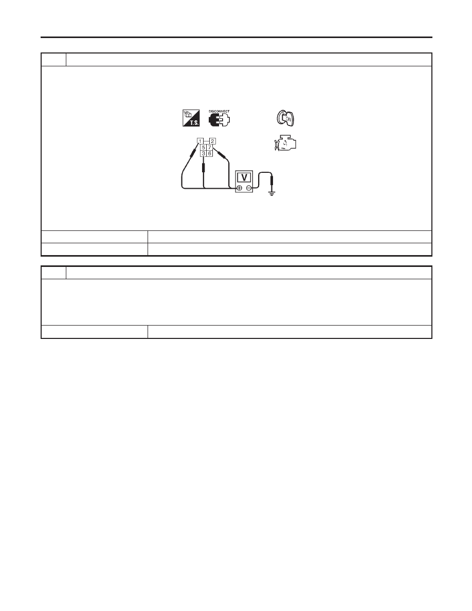
CHECK COOLING FAN POWER SUPPLY CIRCUIT
1. Turn ignition switch “OFF”.
2. Disconnect cooling fan relay-1.
3. Turn ignition switch “ON”.
4. Check voltage between cooling fan relay-1 terminals 1, 3, 7 and ground with CONSULT-II or tester.
SEF727W
Voltage: Battery voltage
OK or NG
OK
©
GO TO 3.
NG
©
GO TO 2.
2
DETECT MALFUNCTIONING PART
Check the following.
I
10A fuse
I
40A fusible links
I
Harness for open or short between cooling fan relay-1 and fuse
I
Harness for open or short between cooling fan relay-1 and battery
©
Repair open circuit or short to ground or short to power in harness or connectors.
DTC P0217 COOLANT OVERTEMPERATURE ENRICHMENT PROTECTION
Diagnostic Procedure (A/T Models) (Cont’d)
EC-304
3
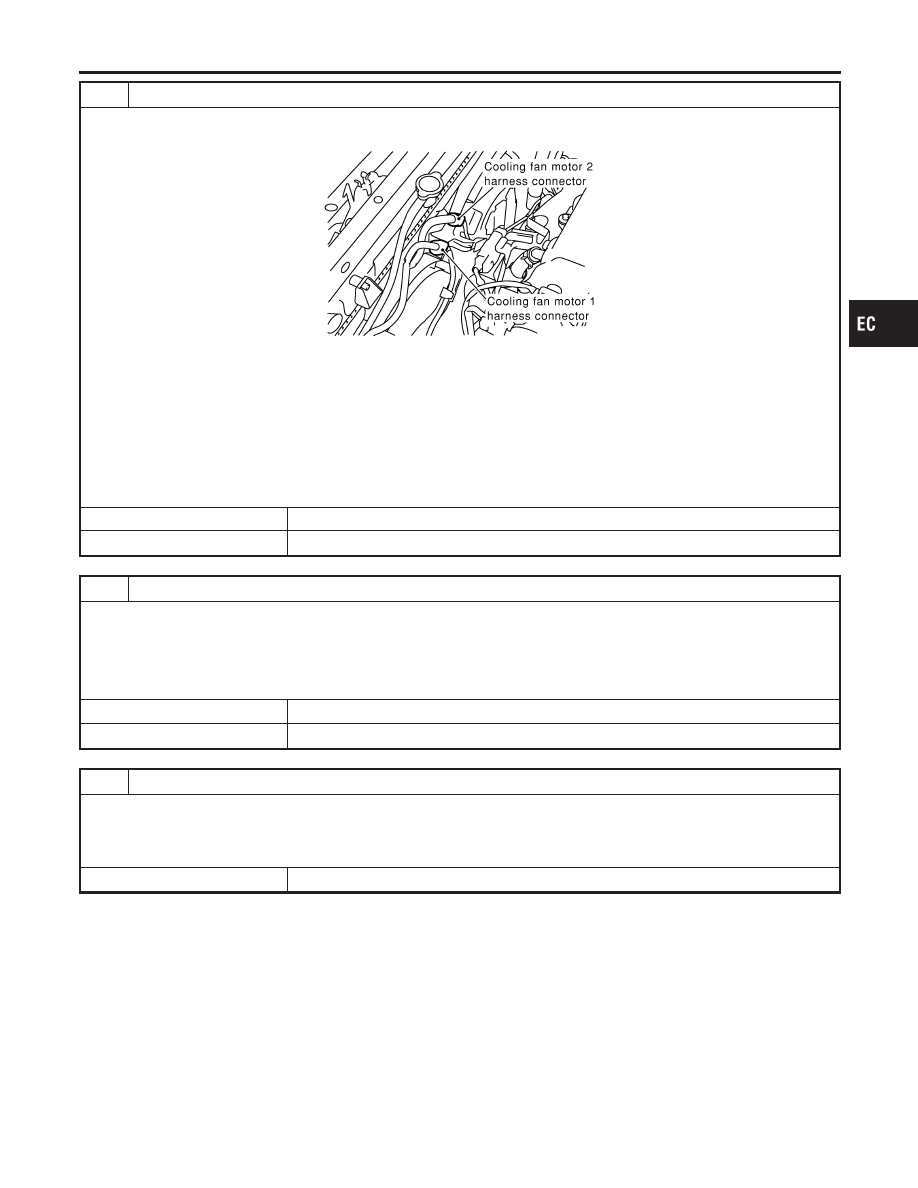
CHECK COOLING FAN MOTOR CIRCUIT FOR OPEN AND SHORT
1. Turn ignition switch “OFF”.
2. Disconnect cooling fan motor-1 harness connector and cooling fan motor-2 harness connector.
SEF854X
3. Check harness continuity between cooling fan relay-1 terminal 6 and cooling fan motor-1 terminal 1, cooling fan
motor-1 terminal 4 and body ground. Refer to Wiring Diagram.
Continuity should exist.
4. Also check harness for short to ground and short to power.
5. Check harness continuity between cooling fan relay-1 terminal 5 and cooling fan motor-2 terminal 1, cooling fan
motor-2 terminal 4 and body ground. Refer to Wiring Diagram.
Continuity should exist.
6. Also check harness for short to ground and short to power.
OK or NG
OK
©
GO TO 4.
NG
©
Repair open circuit or short to ground or short to power in harness or connectors.
4
CHECK COOLING FAN OUTPUT SIGNAL CIRCUIT FOR OPEN AND SHORT
1. Disconnect ECM harness connector.
2. Check harness continuity between ECM terminal 13 and cooling fan relay-1 terminal 2. Refer to Wiring Diagram.
Continuity should exist.
3. Also check harness for short to ground and short to power.
OK or NG
OK
©
GO TO 6.
NG
©
GO TO 5.
5
DETECT MALFUNCTIONING PART
Check the following.
I
Harness connectors E75, M6
I
Harness connectors M49, F23
I
Harness for open or short between cooling fan relay-1 and ECM
©
Repair open circuit or short to ground or short to power in harness or connectors.
GI
MA
EM
LC
FE
CL
MT
AT
AX
SU
BR
ST
RS
BT
HA
SC
EL
IDX
DTC P0217 COOLANT OVERTEMPERATURE ENRICHMENT PROTECTION
Diagnostic Procedure (A/T Models) (Cont’d)
EC-305
6
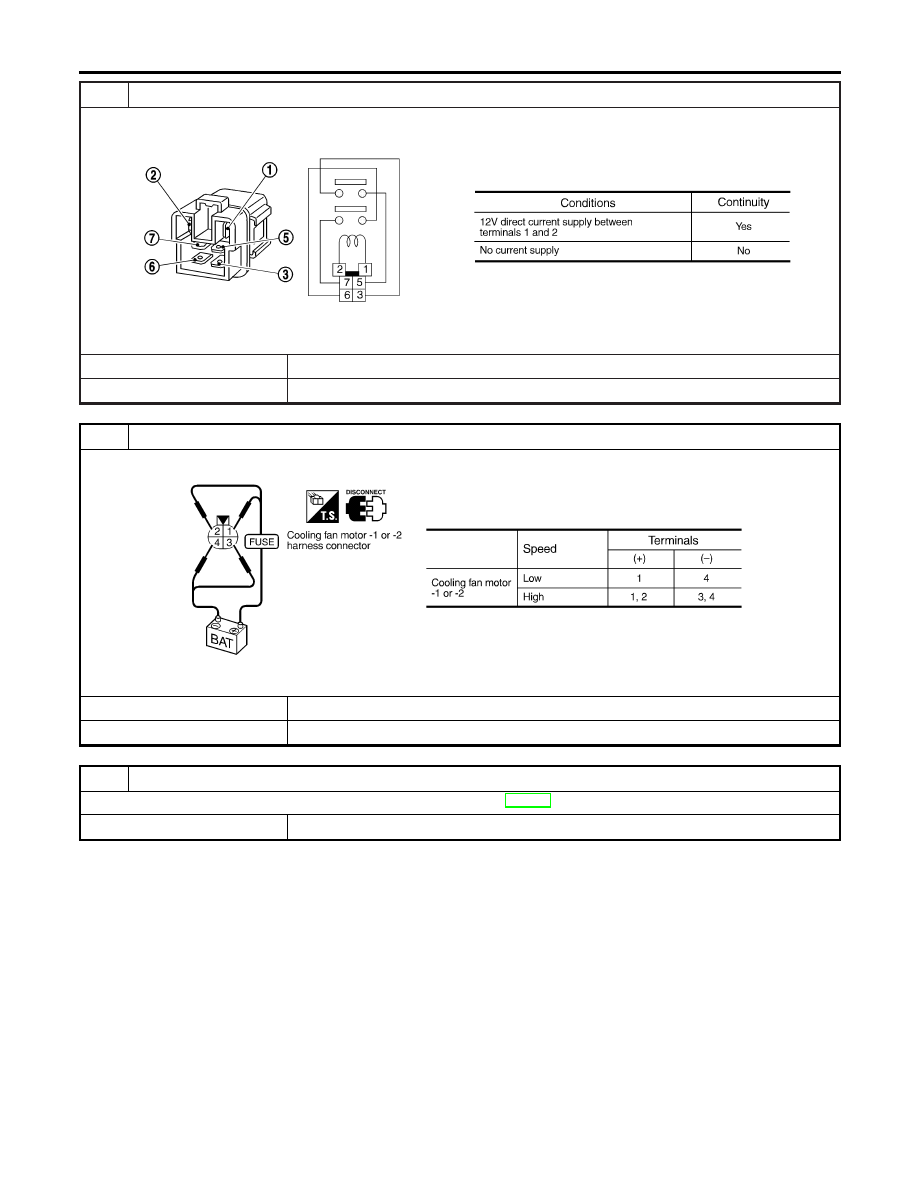
CHECK COOLING FAN RELAY-1
Check continuity between cooling fan relay-1 terminals 3 and 5, 6 and 7 under the following conditions.
SEF591X
OK or NG
OK
©
GO TO 7.
NG
©
Replace cooling fan relay.
7
CHECK COOLING FAN MOTORS-1 AND -2
Supply battery voltage between the following terminals and check operation.
SEF937X
OK or NG
OK
©
GO TO 8.
NG
©
Replace cooling fan motors.
8
CHECK INTERMITTENT INCIDENT
Perform “TROUBLE DIAGNOSIS FOR INTERMITTENT INCIDENT”, EC-146.
©
INSPECTION END
DTC P0217 COOLANT OVERTEMPERATURE ENRICHMENT PROTECTION
Diagnostic Procedure (A/T Models) (Cont’d)
EC-306
Нет комментариевНе стесняйтесь поделиться с нами вашим ценным мнением.
Текст