Infiniti G20 (P11). Manual — part 145
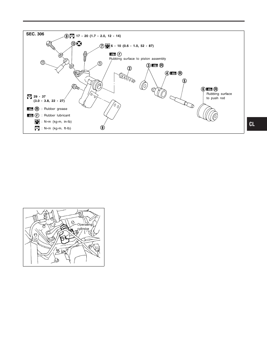
Components
NCCL0019
SCL898
1.
Cylinder body
2.
Piston spring
3.
Piston cup
4.
Piston
5.
Push rod
6.
Dust cover
7.
Air bleeder
8.
Spacer
9.
Union bolt
10. Copper washer
11. Clutch hose
SCL739
Removal
NCCL0020
1.
Drain brake fluid.
CAUTION:
Be careful not to splash brake fluid on painted areas; it may
cause paint damage. If brake fluid is splashed on painted
areas, wash it away with water immediately.
2.
Remove union bolt and clutch hose from operating cylinder.
3.
Remove operating cylinder mounting bolts, and remove cylin-
der from vehicle.
Disassembly
NCCL0021
Remove dust cover, and remove piston assembly from cylinder
body.
GI
MA
EM
LC
EC
FE
MT
AT
AX
SU
BR
ST
RS
BT
HA
SC
EL
IDX
OPERATING CYLINDER
Components
CL-13
Inspection
NCCL0022
Inspect for following, and replace parts if necessary.
I
Damage, foreign material, wear, rust, and pinholes on the cyl-
inder inner surface, piston, and sliding part of piston cup
I
Weak spring
I
Crack and deformation of dust cover
Assembly
NCCL0023
1.
Apply recommended rubber grease to piston cup and piston,
and insert piston assembly.
2.
Install dust cover.
Installation
NCCL0024
Install the components in the reverse order of removal. Adhere to
the operations described below.
CAUTION:
Install the hose without twisting it.
I
The copper washer of the union bolt should not be reused.
Always use a new copper washer for installation.
I
After finishing the operation, bleed air from the clutch
piping. Refer to “Bleeding Procedure”, CL-7.
OPERATING CYLINDER
Inspection
CL-14
SCL729
Removal
NCCL0025
1.
Remove fuel filter mounting bracket.
2.
Remove air cleaner and air duct.
3.
Drain brake fluid.
CAUTION:
Be careful not to splash brake fluid on painted areas; it may
cause paint damage. If brake fluid is splashed on painted
areas, wash it away with water immediately.
4.
Remove flare nut using a flare nut wrench.
5.
Remove clutch hose and clutch tube.
SCL730
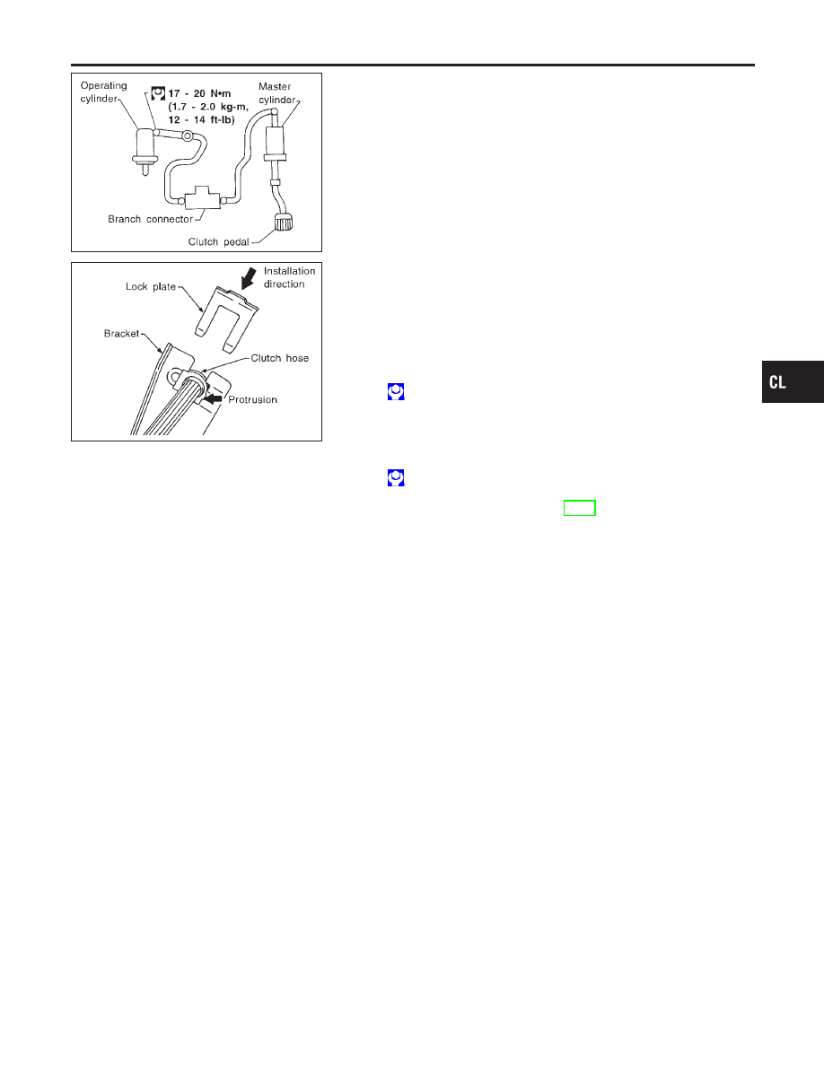
Installation
NCCL0026
1.
When installing clutch hose to bracket, face lock plate in the
correct direction as shown to secure clutch hose.
CAUTION:
Install clutch hose without twisting or bending it.
2.
Tighten flare nut to the specified torque, using a flare nut
wrench.
: 15 - 18 N·m (1.5 - 1.8 kg-m, 11 - 13 ft-lb)
CAUTION:
Be careful not to damage flare nut and clutch tube.
3.
Install clutch hose to operating cylinder, and tighten mounting
bolts to the specified torque.
: 17 - 20 N·m (1.7 - 2.0 kg-m, 12 - 14 ft-lb)
4.
After finishing the operation, bleed air from the clutch piping.
Refer to “Bleeding Procedure”, CL-7.
GI
MA
EM
LC
EC
FE
MT
AT
AX
SU
BR
ST
RS
BT
HA
SC
EL
IDX
PIPING
Removal
CL-15
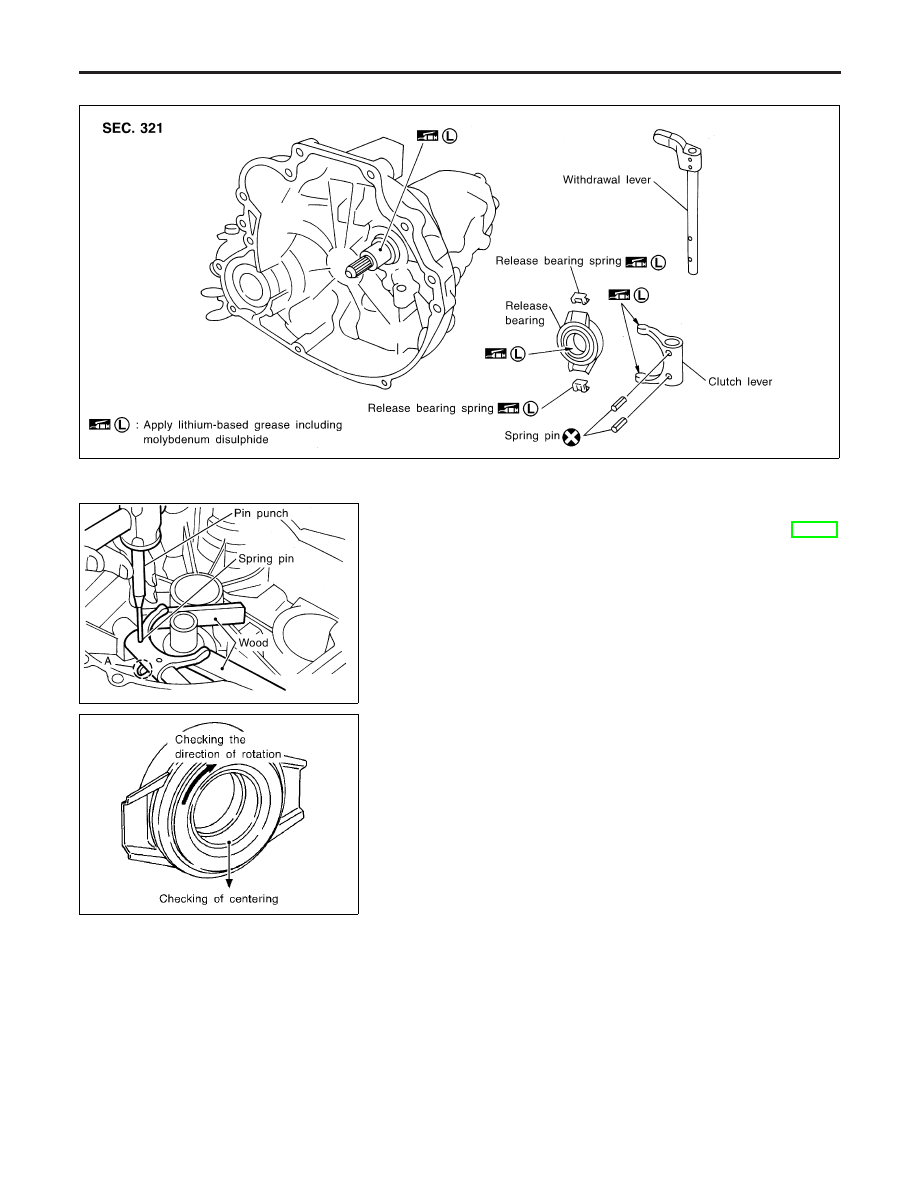
Components
NCCL0027
SCL819
SCL820
Removal
1.
Remove manual transaxle from vehicle. Refer to MT-12,
“Removal”.
2.
Move withdrawal lever enough to remove release bearing, and
remove release bearing from clutch lever.
3.
Support clutch lever claws with an appropriate wood block,
align retaining pin with A in the figure, and drive out spring pin
using a pin punch.
4.
Pull out withdrawal lever and remove clutch lever.
SCL733
Inspection
NCCL0029
I
Replace the release bearing if it is seized, damaged, faulty in
rotation direction, or has poor aligning function.
I
Replace the withdrawal lever if its contact surface is worn
abnormally.
I
Replace the clutch lever if its contact surface is worn abnor-
mally.
I
Replace the dust seal if it is deformed or cracked.
Installation
NCCL0030
CAUTION:
I
Be sure to apply grease to the clutch components.
Otherwise, abnormal noise, poor clutch disengagement,
or clutch damage may occur. Wipe the excess grease off
completely, because it may cause the clutch components
to slip and shudder.
I
Keep the clutch disc facing, pressure plate, and flywheel
free of oil and grease.
CLUTCH RELEASE MECHANISM
Components
CL-16
Нет комментариевНе стесняйтесь поделиться с нами вашим ценным мнением.
Текст