Infiniti G20 (P11). Manual — part 143
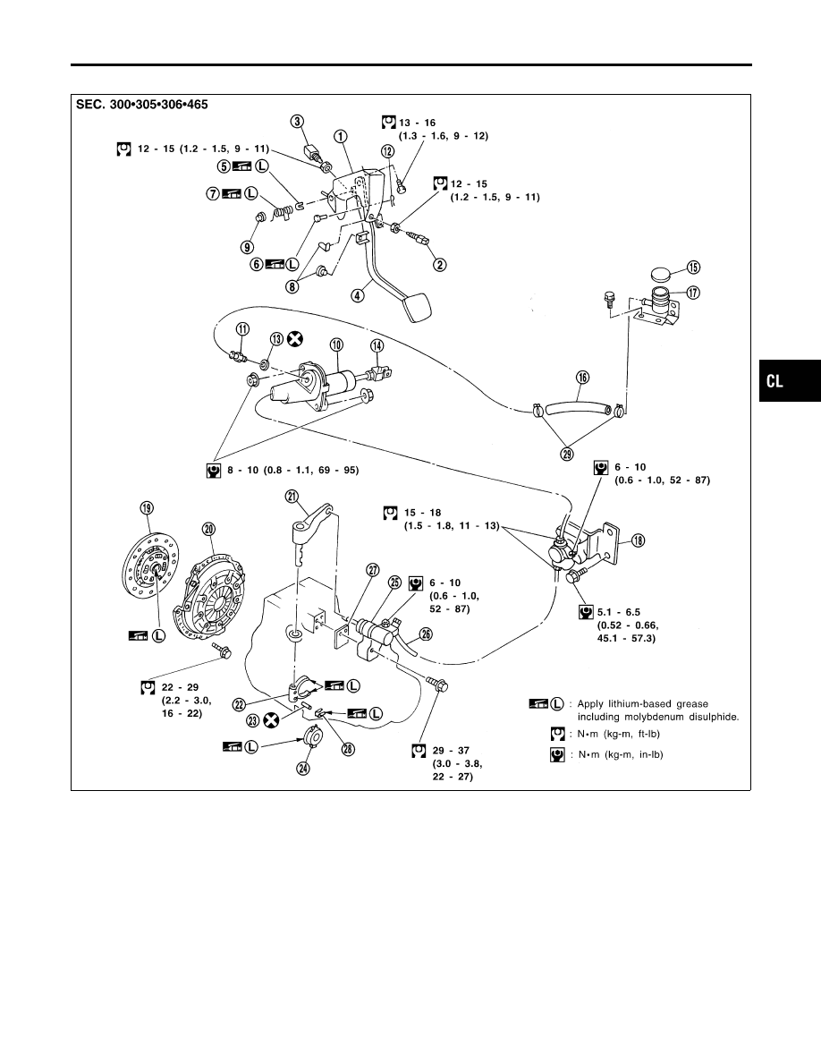
Components
NCCL0005
SCL818
1.
Clutch pedal bracket
2.
ASCD clutch switch
3.
Clutch interlock switch
4.
Clutch pedal
5.
Bush
6.
Clevis pin
7.
Assist spring
8.
Stopper rubber
9.
Bush
10. Clutch master cylinder
11. Nipple
12. Snap pin
13. Seal
14. Clevis
15. Reservoir cap
16. Hose
17. Reservoir tank
18. Clutch damper
19. Clutch disc
20. Clutch cover
21. Withdrawal lever
22. Clutch lever
23. Spring pin
24. Release bearing
25. Operating cylinder
26. Clutch hose
27. Spacer
28. Release bearing spring
29. Hose clamp
GI
MA
EM
LC
EC
FE
MT
AT
AX
SU
BR
ST
RS
BT
HA
SC
EL
IDX
CLUTCH SYSTEM
Components
CL-5
SCL799
Inspection and Adjustment
NCCL0006
ADJUSTING CLUTCH PEDAL
NCCL0006S01
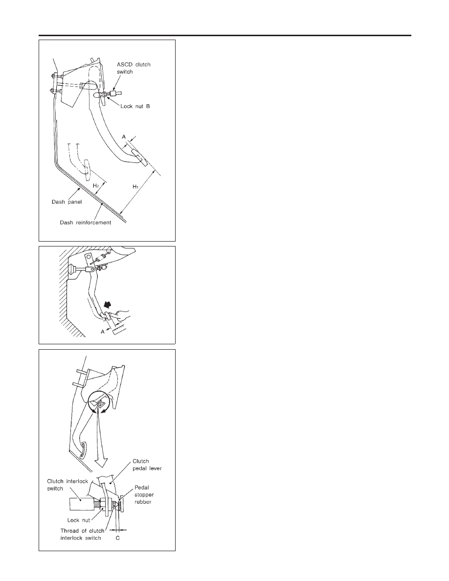
Pedal Height
NCCL0006S0101
1.
Verify that clutch pedal height “H
1
” is within specification.
I
Measure distance between the upper surface of dash rein-
forcement and pedal.
Pedal height “H
1
”:
158 - 168 mm (6.22 - 6.61 in)
SCL702
2.
Adjust pedal free play with master cylinder push rod. Then
tighten lock nut.
Pedal free play “A”:
9 - 16 mm (0.35 - 0.63 in)
I
Push or step on clutch pedal until resistance is felt, and check
the distance the pedal moves.
SCL800
3.
Adjust clearance “C” shown in the figure while fully depressing
clutch pedal fully.
Clearance C:
0.1 - 1.0 mm (0.004 - 0.039 in)
CLUTCH SYSTEM
Inspection and Adjustment
CL-6
SCL721
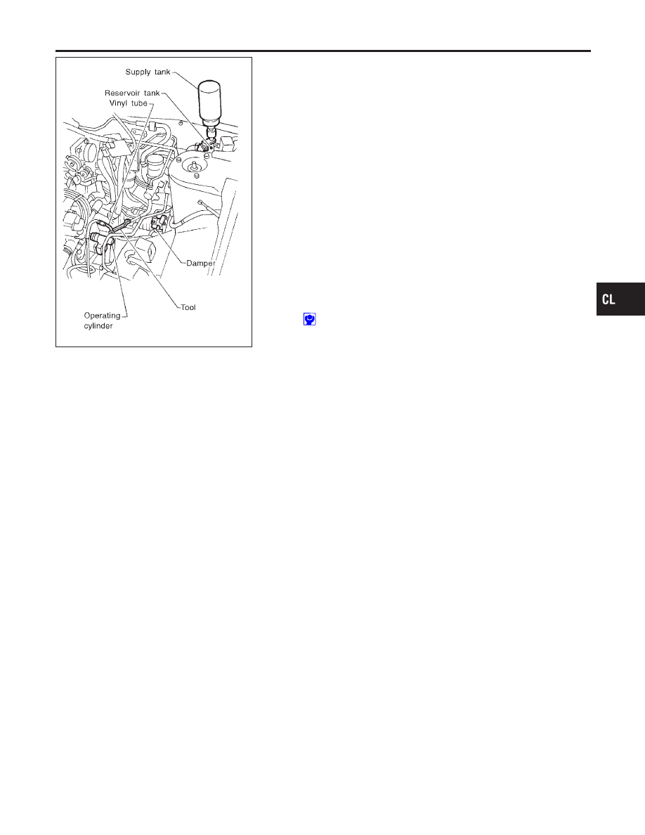
BLEEDING PROCEDURE
NCCL0006S02
1.
Bleed air from clutch damper according to the following proce-
dure.
I
Carefully monitor fluid level at master cylinder during
bleeding operation.
a.
Top up reservoir with recommended brake fluid.
b.
Connect a transparent vinyl tube to air bleeder valve.
c.
Slowly depress the clutch pedal to its full stroke and release it
completely. Repeat this operation several times at 2 to 3 sec-
onds intervals.
d.
Open the air bleeder with the clutch pedal fully depressed.
e.
Close the air bleeder.
f.
Release the clutch pedal and wait at least 5 seconds.
g.
Repeat steps c through f mentioned above, then air bubbles
will no longer appear at the damper in the brake fluid.
2.
Bleed air from clutch operating cylinder according to the above
procedure.
3.
Repeat the above bleeding procedure 1 and 2 several times.
Air bleeder valve tightening torque:
: 6 - 10 N·m (0.6 - 1.0 kg-m, 52 - 87 in-lb)
GI
MA
EM
LC
EC
FE
MT
AT
AX
SU
BR
ST
RS
BT
HA
SC
EL
IDX
CLUTCH SYSTEM
Inspection and Adjustment (Cont’d)
CL-7
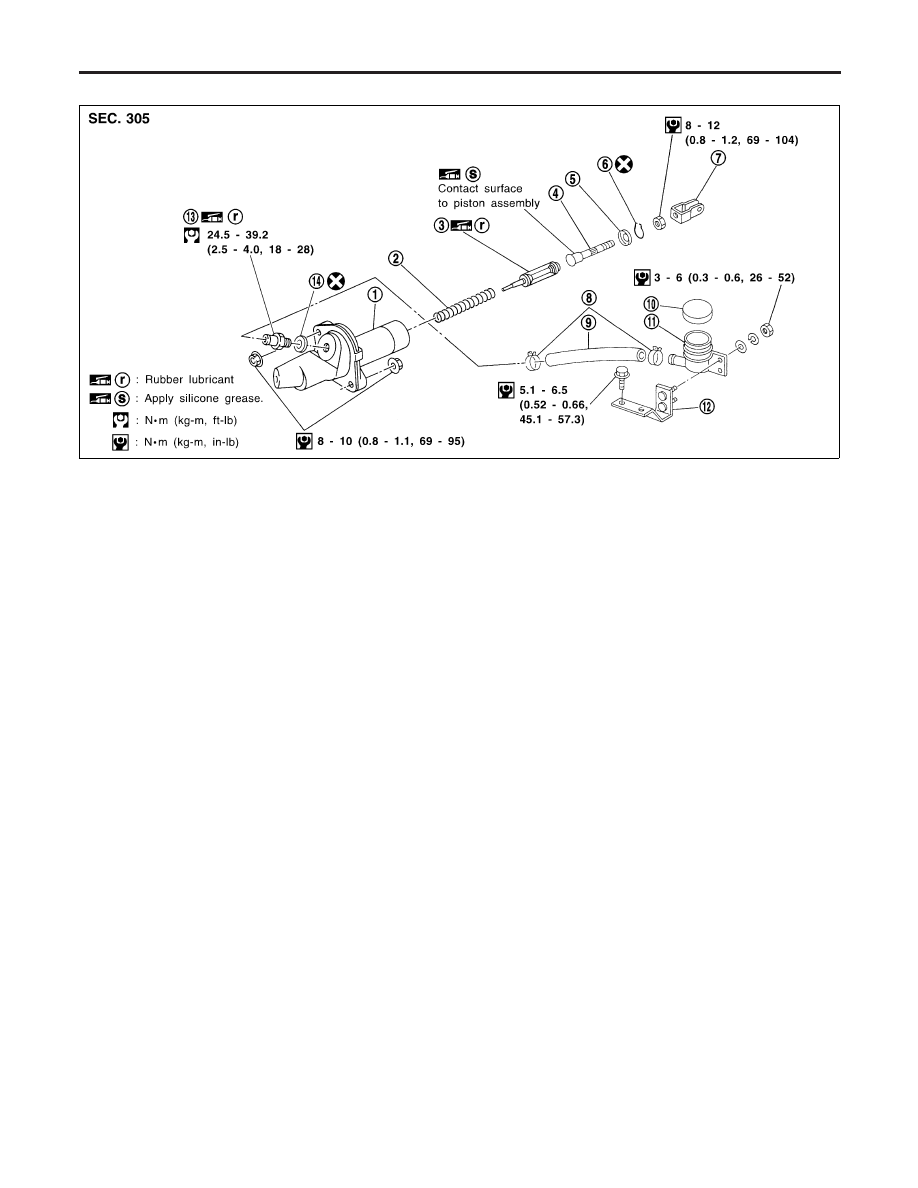
Components
NCCL0007
SCL897
1.
Clutch master cylinder
2.
Return spring
3.
Piston assembly
4.
Push rod
5.
Stopper
6.
Stopper ring
7.
Clevis
8.
Hose clamp
9.
Hose
10. Reservoir cap
11. Reservoir tank
12. Bracket
13. Nipple
14. Seal
Removal
NCCL0008
1.
Drain brake fluid.
CAUTION:
Be careful not to splash brake fluid on painted areas; it may
cause paint damage. If brake fluid is splashed on painted
areas, wash it away with water immediately.
2.
Remove clutch tube using a flare nut wrench.
3.
Remove snap pin between clutch pedal and push rod, and
remove clevis pin.
4.
Unscrew master cylinder assembly mounting nuts and reser-
voir tank bracket mounting bolts to remove master cylinder
assembly from vehicle.
CLUTCH MASTER CYLINDER
Components
CL-8
Нет комментариевНе стесняйтесь поделиться с нами вашим ценным мнением.
Текст