Infiniti G20 (P11). Manual — part 67
2
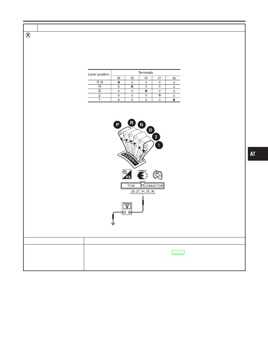
CHECK PNP SWITCH CIRCUIT (Without CONSULT-II)
Without CONSULT-II
1. Turn ignition switch to “ON” position. (Do not start engine.)
2. Check voltage between TCM terminals 26, 27, 34, 35, 36 and ground while moving selector lever through each posi-
tion.
Voltage:
B: Battery voltage
0: 0V
MTBL0138
SAT470J
OK or NG
OK
©
GO TO 4.
NG
©
Check the following items:
I
PNP switch (Refer to “Component Inspection”, AT-270.)
I
Harness for short or open between ignition switch and PNP switch (Main harness)
I
Harness for short or open between PNP switch and TCM (Main harness)
I
Diode (P, N positions)
GI
MA
EM
LC
EC
FE
CL
MT
AX
SU
BR
ST
RS
BT
HA
SC
EL
IDX
TROUBLE DIAGNOSES FOR SYMPTOMS
21. TCM Self-diagnosis Does Not Activate (PNP, Overdrive Control and Throttle Position Switches Circuit Checks) (Cont’d)
AT-265
3
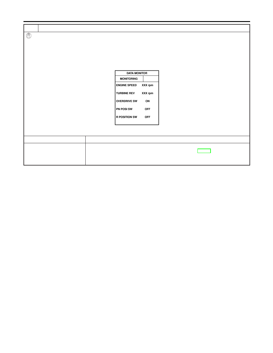
CHECK OVERDRIVE CONTROL SWITCH CIRCUIT (With CONSULT-II)
With CONSULT-II
1. Turn ignition switch to “ON” position.
(Do not start engine.)
2. Select “TCM INPUT SIGNALS” in “DATA MONITOR” mode for “A/T” with CONSULT-II.
3. Read out “OVERDRIVE SWITCH”.
Check the signal of the overdrive control switch is indicated properly.
(Overdrive control switch “ON” displayed on CONSULT-II means overdrive “OFF”.)
SAT645J
OK or NG
OK
©
GO TO 5.
NG
©
Check the following items:
I
Overdrive control switch (Refer to “Component Inspection”, AT-270.)
I
Harness for short or open between TCM and overdrive control switch (Main harness)
I
Harness of ground circuit for overdrive control switch (Main harness) for short or open
TROUBLE DIAGNOSES FOR SYMPTOMS
21. TCM Self-diagnosis Does Not Activate (PNP, Overdrive Control and Throttle Position Switches Circuit Checks) (Cont’d)
AT-266
4
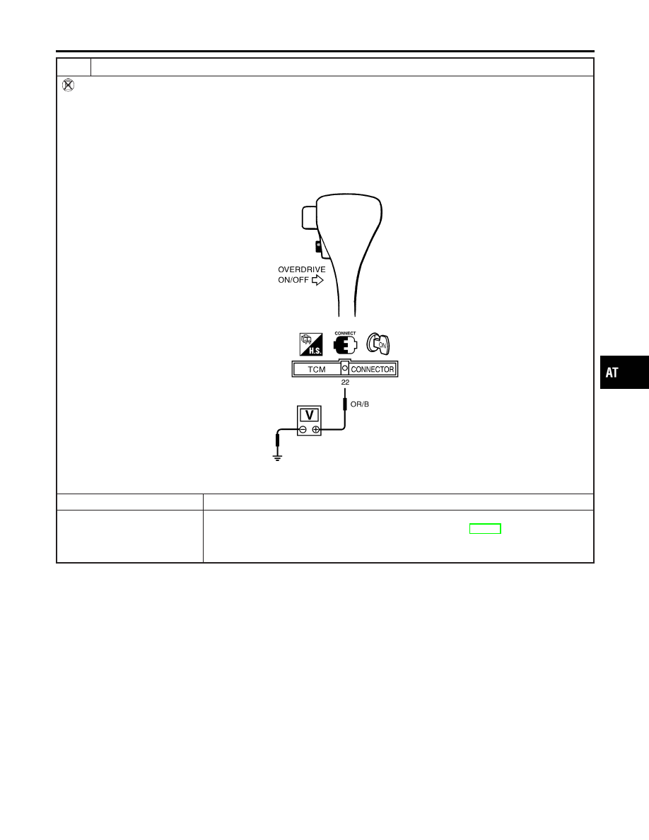
CHECK OVERDRIVE CONTROL SWITCH CIRCUIT (Without CONSULT-II)
Without CONSULT-II
1. Turn ignition switch to “ON” position.
(Do not start engine.)
2. Check voltage between TCM terminal 22 and ground when overdrive control switch is “ON” and “OFF”.
Voltage:
Switch position “ON”:
Battery voltage
Switch position “OFF”:
1V or less
SAT471JA
OK or NG
OK
©
GO TO 6.
NG
©
Check the following items:
I
Overdrive control switch (Refer to “Component Inspection”, AT-270.)
I
Harness for short or open between TCM and overdrive control switch (Main harness)
I
Harness of ground circuit for overdrive control switch (Main harness) for short or open
GI
MA
EM
LC
EC
FE
CL
MT
AX
SU
BR
ST
RS
BT
HA
SC
EL
IDX
TROUBLE DIAGNOSES FOR SYMPTOMS
21. TCM Self-diagnosis Does Not Activate (PNP, Overdrive Control and Throttle Position Switches Circuit Checks) (Cont’d)
AT-267
5
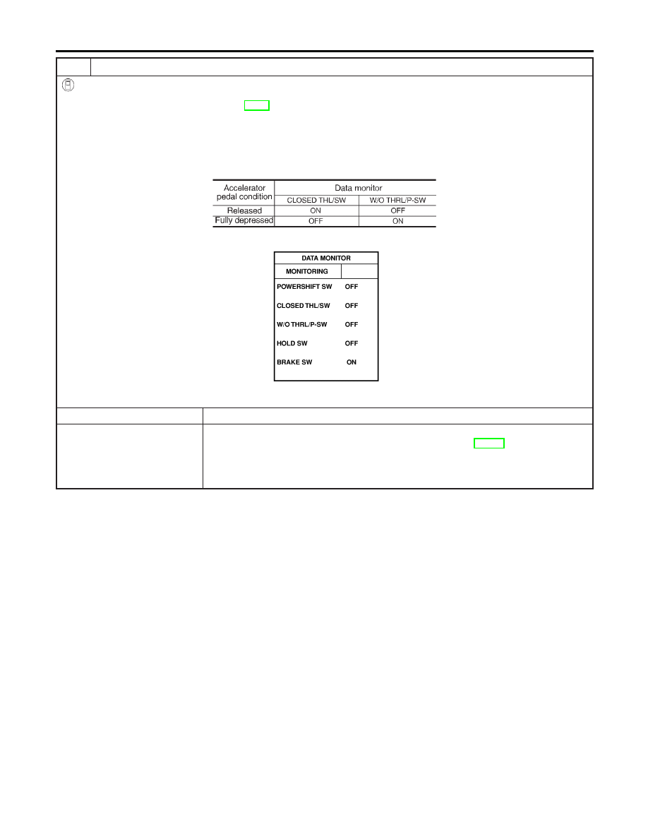
CHECK THROTTLE POSITION SWITCH CIRCUIT (With CONSULT-II)
With CONSULT-II
1. Apply vacuum to the throttle opener, then check the following. Refer from step 1 to 5 of “Preparation”, “TCM SELF-DI-
AGNOSTIC PROCEDURE (No Tools)”, AT-49.
2. Turn ignition switch to “ON” position.
(Do not start engine.)
3. Select “TCM INPUT SIGNALS” in “DATA MONITOR” mode for “A/T” with CONSULT-II.
4. Read out “CLOSED THL/SW” and “W/O THRL/P-SW” depressing and releasing accelerator pedal.
Check the signal of throttle position switch is indicated properly.
MTBL0011
SAT702J
OK or NG
OK
©
GO TO 7.
NG
©
Check the following items:
I
Throttle position switch — Refer to “Component Inspection”, AT-270.
I
Harness for short or open between ignition switch and throttle position switch (Main
harness)
I
Harness for short or open between throttle position switch and TCM (Main harness)
TROUBLE DIAGNOSES FOR SYMPTOMS
21. TCM Self-diagnosis Does Not Activate (PNP, Overdrive Control and Throttle Position Switches Circuit Checks) (Cont’d)
AT-268
Нет комментариевНе стесняйтесь поделиться с нами вашим ценным мнением.
Текст