Infiniti G20 (P11). Manual — part 154
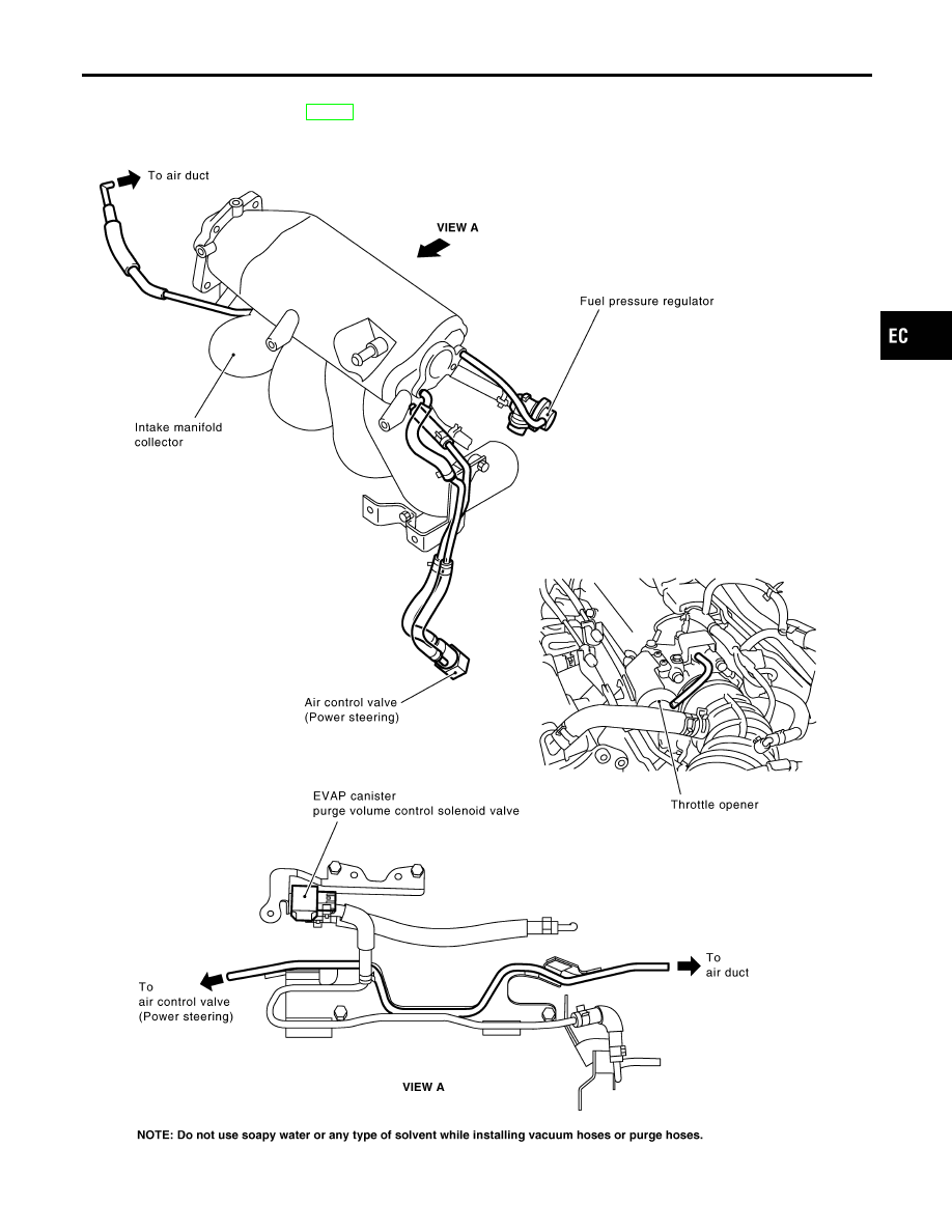
Vacuum Hose Drawing
NCEC0012
Refer to “System Diagram” on EC-26 for vacuum control system.
SEF914Z
GI
MA
EM
LC
FE
CL
MT
AT
AX
SU
BR
ST
RS
BT
HA
SC
EL
IDX
ENGINE AND EMISSION CONTROL OVERALL SYSTEM
Vacuum Hose Drawing
EC-27

System Chart
NCEC0013
Input (Sensor)
ECM Function
Output (Actuator)
I
Camshaft position sensor
I
Mass air flow sensor
I
Engine coolant temperature sensor
I
Heated oxygen sensor 1 (front)
I
Ignition switch
I
Throttle position sensor
I
PNP switch
I
Air conditioner switch
I
Knock sensor
I
EGR temperature sensor*1
I
Crankshaft position sensor (OBD)*1
I
EVAP control system pressure sensor*1
I
Fuel tank temperature sensor*1
I
Battery voltage
I
Power steering oil pressure switch
I
Vehicle speed sensor
I
Intake air temperature sensor
I
Heated oxygen sensor 2 (rear)*3
I
TCM (Transmission control module)*2
I
Closed throttle position switch*4
I
Electrical load
I
Fuel level sensor*1
I
Refrigerant pressure sensor
Fuel injection & mixture ratio control
Injectors
Distributor ignition system
Power transistor
Idle air control system
IACV-AAC valve
Fuel pump control
Fuel pump relay
On board diagnostic system
Malfunction indicator lamp
(On the instrument panel)
EGR control
EGR volume control valve
Heated oxygen sensor 1 heater (front)
control
Heated oxygen sensor 1 heater
(front)
Heated oxygen sensor 2 heater (rear) con-
trol
Heated oxygen sensor 2 heater
(rear)
EVAP canister purge flow control
EVAP canister purge volume con-
trol solenoid valve
Cooling fan control
Cooling fan relays
Air conditioning cut control
Air conditioner relay
ON BOARD DIAGNOSIS for EVAP system
I
EVAP canister vent control
valve
I
Vacuum cut valve bypass valve
*1: These sensors are not used to control the engine system. They are used only for the on board diagnosis.
*2: The DTC related to A/T will be sent to ECM.
*3: Under normal conditions, this sensor is not for engine control operation.
*4: This switch will operate in place of the throttle position sensor to control EVAP parts if the sensor malfunctions.
ENGINE AND EMISSION CONTROL OVERALL SYSTEM
System Chart
EC-28
Multiport Fuel Injection (MFI) System
DESCRIPTION
NCEC0014
Input/Output Signal Chart
NCEC0014S01
Sensor
Input Signal to ECM
ECM func-
tion
Actuator
Camshaft position sensor
Engine speed and piston position
Fuel injec-
tion & mix-
ture ratio
control
Injector
Mass air flow sensor
Amount of intake air
Engine coolant temperature sensor
Engine coolant temperature
Heated oxygen sensor 1 (front)
Density of oxygen in exhaust gas
Throttle position sensor
Throttle position
Throttle valve idle position
PNP switch
Gear position
Vehicle speed sensor
Vehicle speed
Ignition switch
Start signal
Air conditioner switch
Air conditioner operation
Knock sensor
Engine knocking condition
Electrical load
Electrical load signal
Battery
Battery voltage
Power steering oil pressure switch
Power steering operation
Heated oxygen sensor 2 (rear)*
Density of oxygen in exhaust gas
* Under normal conditions, this sensor is not for engine control operation.
Basic Multiport Fuel Injection System
NCEC0014S02
The amount of fuel injected from the fuel injector is determined by the ECM. The ECM controls the length of
time the valve remains open (injection pulse duration). The amount of fuel injected is a program value in the
ECM memory. The program value is preset by engine operating conditions. These conditions are determined
by input signals (for engine speed and intake air) from both the camshaft position sensor and the mass air
flow sensor.
Various Fuel Injection Increase/Decrease Compensation
NCEC0014S03
In addition, the amount of fuel injected is compensated to improve engine performance under various oper-
ating conditions as listed below.
<Fuel increase>
I
During warm-up
I
When starting the engine
I
During acceleration
I
Hot-engine operation
I
When selector lever is changed from “N” to “D” (A/T models only)
I
High-load, high-speed operation
<Fuel decrease>
I
During deceleration
I
During high engine speed operation
I
During high vehicle speed operation (M/T models)
I
Extremely high engine coolant temperature
GI
MA
EM
LC
FE
CL
MT
AT
AX
SU
BR
ST
RS
BT
HA
SC
EL
IDX
ENGINE AND EMISSION BASIC CONTROL SYSTEM DESCRIPTION
Multiport Fuel Injection (MFI) System
EC-29
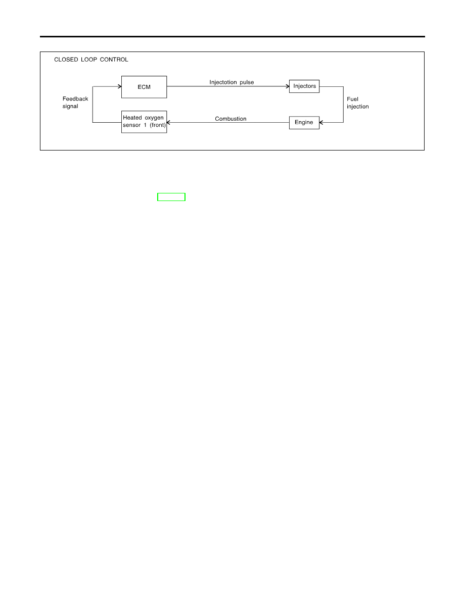
Mixture Ratio Feedback Control (Closed loop control)
NCEC0014S04
SEF336WA
The mixture ratio feedback system provides the best air-fuel mixture ratio for driveability and emission con-
trol. The three way catalyst can then better reduce CO, HC and NOx emissions. This system uses a heated
oxygen sensor 1 (front) in the exhaust manifold to monitor if the engine operation is rich or lean. The ECM
adjusts the injection pulse width according to the sensor voltage signal. For more information about the heated
oxygen sensor 1 (front), refer to EC-196. This maintains the mixture ratio within the range of stoichiometric
(ideal air-fuel mixture).
This stage is referred to as the closed loop control condition.
Heated oxygen sensor 2 (rear) is located downstream of the three way catalyst. Even if the switching char-
acteristics of the heated oxygen sensor 1 (front) shift, the air-fuel ratio is controlled to stoichiometric by the
signal from the heated oxygen sensor 2 (rear).
Open Loop Control
NCEC0014S05
The open loop system condition refers to when the ECM detects any of the following conditions. Feedback
control stops in order to maintain stabilized fuel combustion.
I
Deceleration and acceleration
I
High-load, high-speed operation
I
Malfunction of heated oxygen sensor 1 (front) or its circuit
I
Insufficient activation of heated oxygen sensor 1 (front) at low engine coolant temperature
I
High engine coolant temperature
I
During warm-up
I
When starting the engine
Mixture Ratio Self-learning Control
NCEC0014S06
The mixture ratio feedback control system monitors the mixture ratio signal transmitted from the heated oxy-
gen sensor 1 (front). This feedback signal is then sent to the ECM. The ECM controls the basic mixture ratio
as close to the theoretical mixture ratio as possible. However, the basic mixture ratio is not necessarily con-
trolled as originally designed. Both manufacturing differences (i.e., mass air flow sensor hot film) and charac-
teristic changes during operation (i.e., injector clogging) directly affect mixture ratio.
Accordingly, the difference between the basic and theoretical mixture ratios is monitored in this system. This
is then computed in terms of “injection pulse duration” to automatically compensate for the difference between
the two ratios.
“Fuel trim” refers to the feedback compensation value compared against the basic injection duration. Fuel trim
includes short term fuel trim and long term fuel trim.
“Short term fuel trim” is the short-term fuel compensation used to maintain the mixture ratio at its theoretical
value. The signal from the heated oxygen sensor 1 (front) indicates whether the mixture ratio is RICH or LEAN
compared to the theoretical value. The signal then triggers a reduction in fuel volume if the mixture ratio is
rich, and an increase in fuel volume if it is lean.
“Long term fuel trim” is overall fuel compensation carried out long-term to compensate for continual deviation
of the short term fuel trim from the central value. Such deviation will occur due to individual engine differences,
wear over time and changes in the usage environment.
ENGINE AND EMISSION BASIC CONTROL SYSTEM DESCRIPTION
Multiport Fuel Injection (MFI) System (Cont’d)
EC-30
Нет комментариевНе стесняйтесь поделиться с нами вашим ценным мнением.
Текст