Infiniti G20 (P11). Manual — part 155
Fuel Injection Timing
NCEC0014S07
SEF337W
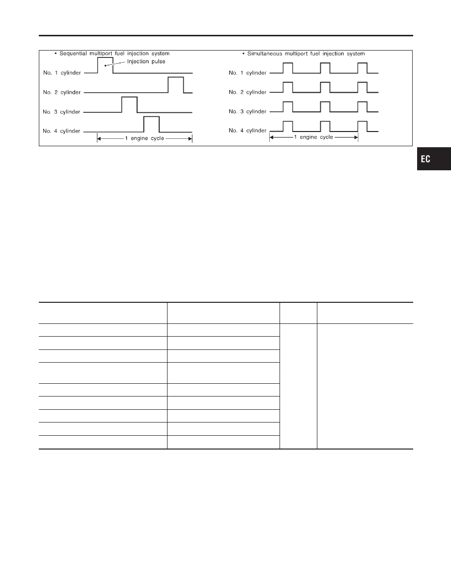
Two types of systems are used.
Sequential Multiport Fuel Injection System
NCEC0014S0701
Fuel is injected into each cylinder during each engine cycle according to the firing order. This system is used
when the engine is running.
Simultaneous Multiport Fuel Injection System
NCEC0014S0702
Fuel is injected simultaneously into all four cylinders twice each engine cycle. In other words, pulse signals of
the same width are simultaneously transmitted from the ECM.
The four injectors will then receive the signals two times for each engine cycle.
This system is used when the engine is being started and/or if the fail-safe system (CPU) is operating.
Fuel Shut-off
NCEC0014S08
Fuel to each cylinder is cut off during deceleration or operation of the engine at excessively high speeds.
Distributor Ignition (DI) System
DESCRIPTION
NCEC0015
Input/Output Signal Chart
NCEC0015S01
Sensor
Input Signal to ECM
ECM func-
tion
Actuator
Camshaft position sensor
Engine speed and piston position
Ignition tim-
ing control
Power transistor
Mass air flow sensor
Amount of intake air
Engine coolant temperature sensor
Engine coolant temperature
Throttle position sensor
Throttle position
Throttle valve idle position
Vehicle speed sensor
Vehicle speed
Ignition switch
Start signal
Knock sensor
Engine knocking
PNP switch
Gear position
Battery
Battery voltage
GI
MA
EM
LC
FE
CL
MT
AT
AX
SU
BR
ST
RS
BT
HA
SC
EL
IDX
ENGINE AND EMISSION BASIC CONTROL SYSTEM DESCRIPTION
Multiport Fuel Injection (MFI) System (Cont’d)
EC-31
System Description
NCEC0015S02
SEF742M
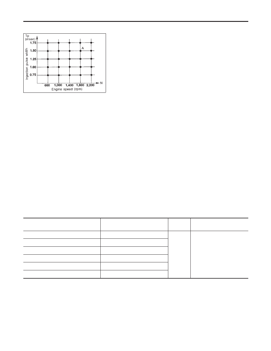
The ignition timing is controlled by the ECM to maintain the best air-fuel ratio for every running condition of
the engine. The ignition timing data is stored in the ECM. This data forms the map shown above.
The ECM receives information such as the injection pulse width and camshaft position sensor signal. Com-
puting this information, ignition signals are transmitted to the power transistor.
e.g.,
N: 1,800 rpm, Tp: 1.50 msec
A°BTDC
During the following conditions, the ignition timing is revised by the ECM according to the other data stored
in the ECM.
I
At starting
I
During warm-up
I
At idle
I
At low battery voltage
I
During acceleration
The knock sensor retard system is designed only for emergencies. The basic ignition timing is programmed
within the anti-knocking zone, if recommended fuel is used under dry conditions. The retard system does not
operate under normal driving conditions.
If engine knocking occurs, the knock sensor monitors the condition. The signal is transmitted to the ECM. The
ECM retards the ignition timing to eliminate the knocking condition.
Air Conditioning Cut Control
DESCRIPTION
NCEC0016
Input/Output Signal Chart
NCEC0016S01
Sensor
Input Signal to ECM
ECM func-
tion
Actuator
Air conditioner switch
Air conditioner “ON” signal
Air condi-
tioner cut
control
Air conditioner relay
PNP switch
Neutral position
Throttle position sensor
Throttle valve opening angle
Camshaft position sensor
Engine speed
Engine coolant temperature sensor
Engine coolant temperature
Ignition switch
Start signal
System Description
NCEC0016S02
This system improves engine operation when the air conditioner is used.
Under the following conditions, the air conditioner is turned off.
I
When the accelerator pedal is fully depressed.
I
When cranking the engine.
I
At high engine speeds.
I
When the engine coolant temperature becomes excessively high.
I
When operating power steering during low engine speed or low vehicle speed.
I
When engine speed is excessively low.
ENGINE AND EMISSION BASIC CONTROL SYSTEM DESCRIPTION
Distributor Ignition (DI) System (Cont’d)
EC-32
Fuel Cut Control (at no load & high engine
speed)
DESCRIPTION
NCEC0017
Input/Output Signal Chart
NCEC0017S01
Sensor
Input Signal to ECM
ECM func-
tion
Actuator
Vehicle speed sensor
Vehicle speed
Fuel cut
control
Injectors
PNP switch
Neutral position
Throttle position sensor
Throttle position
Engine coolant temperature sensor
Engine coolant temperature
Camshaft position sensor
Engine speed
If the engine speed is above 3,950 rpm with no load, (for example, in Neutral and engine speed over 4,000
rpm) fuel will be cut off after some time. The exact time when the fuel is cut off varies based on engine speed.
Fuel cut will operate until the engine speed reaches 1,150 rpm, then fuel cut is cancelled.
NOTE:
This function is different from deceleration control listed under “Multiport Fuel Injection (MFI) System”,
EC-29.
Evaporative Emission System
DESCRIPTION
NCEC0018
SEF569XA
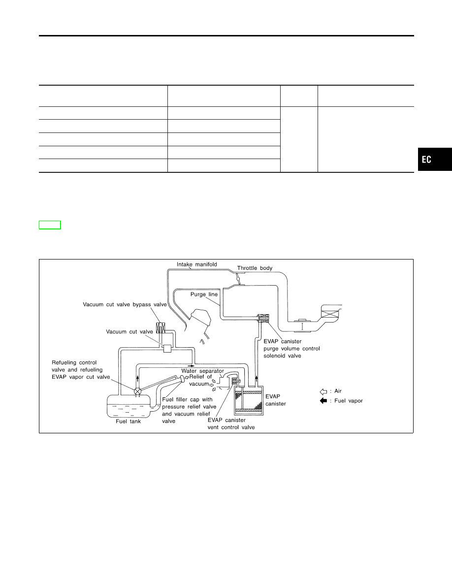
The evaporative emission system is used to reduce hydrocarbons emitted into the atmosphere from the fuel
system. This reduction of hydrocarbons is accomplished by activated charcoals in the EVAP canister.
The fuel vapor in the sealed fuel tank is led into the EVAP canister which contains activated carbon and the
vapor is stored there when the engine is not operating or when refueling to the fuel tank.
The vapor in the EVAP canister is purged by the air through the purge line to the intake manifold when the
engine is operating.
EVAP canister purge volume control solenoid valve is controlled by ECM. When the engine operates, the flow
rate of vapor controlled by EVAP canister purge volume control solenoid valve is proportionally regulated as
the air flow increases.
EVAP canister purge control solenoid valve also shuts off the vapor purge line during decelerating and idling.
GI
MA
EM
LC
FE
CL
MT
AT
AX
SU
BR
ST
RS
BT
HA
SC
EL
IDX
ENGINE AND EMISSION BASIC CONTROL SYSTEM DESCRIPTION
Fuel Cut Control (at no load & high engine speed)
EC-33
SEF396T
INSPECTION
NCEC0019
EVAP Canister
NCEC0019S01
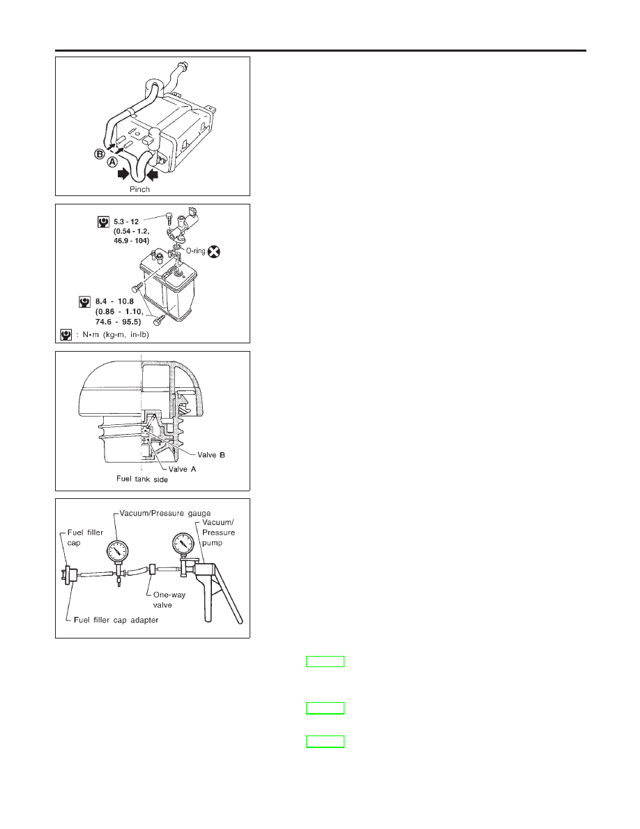
Check EVAP canister as follows:
1.
Pinch the fresh air hose.
2.
Blow air into port A and check that air flows freely through port
B.
AEC778A
Tightening Torque
NCEC0019S02
Tighten EVAP canister as shown in the figure.
Make sure new O-ring is installed properly between EVAP can-
ister and EVAP canister vent control valve.
SEF427N
SEF943S
Fuel Tank Vacuum Relief Valve (Built into fuel filler cap)
NCEC0019S03
1.
Wipe clean valve housing.
2.
Check valve opening pressure and vacuum.
Pressure:
15.3 - 20.0 kPa (0.156 - 0.204 kg/cm
2
, 2.22 - 2.90 psi)
Vacuum:
−6.0 to −3.4 kPa (−0.061 to −0.035 kg/cm
2
, −0.87 to
−0.49 psi)
3.
If out of specification, replace fuel filler cap as an assembly.
CAUTION:
Use only a genuine NISSAN fuel filler cap as a replacement. If
an incorrect fuel filler cap is used, the MIL may come on.
Vacuum Cut Valve and Vacuum Cut Valve Bypass Valve
NCEC0019S05
Refer to EC-568.
Evaporative Emission (EVAP) Canister Purge Volume
Control Solenoid Valve
NCEC0019S06
Refer to EC-382.
Fuel Tank Temperature Sensor
NCEC0019S08
Refer to EC-286.
ENGINE AND EMISSION BASIC CONTROL SYSTEM DESCRIPTION
Evaporative Emission System (Cont’d)
EC-34
Нет комментариевНе стесняйтесь поделиться с нами вашим ценным мнением.
Текст