Infiniti G20 (P11). Manual — part 523
STEERING SYSTEM
CONTENTS
PRECAUTIONS . . . . . . . . . . . . . . . ...2
Supplemental Restraint System (SRS)
. . . ...2
Precautions for Steering System. . . . . . . . .2
PREPARATION . . . . . . . . . . . . . . . ...3
Special Service Tools . . . . . . . . . . . . ..3
Commercial Service Tools . . . . . . . . . . ...4
NOISE, VIBRATION AND HARSHNESS (NVH)
TROUBLESHOOTING . . . . . . . . . . . . . .5
NVH Troubleshooting Chart. . . . . . . . . . .5
ON-VEHICLE SERVICE . . . . . . . . . . . . ..6
Checking Steering Wheel Play. . . . . . . . . 6
Checking Neutral Position on Steering Wheel . . . 6
. . . . . . . . . . . . . . 6
. . . . . . . . . . . . . . . ...6
Front Wheel Turning Angle. . . . . . . . . . ..6
Checking Gear Housing Movement . . . . . . . 6
Checking and Adjusting Drive Belts . . . . . . . 7
Checking Fluid Level . . . . . . . . . . . . ...7
Checking Fluid Leakage . . . . . . . . . . . ..7
Bleeding Hydraulic System. . . . . . . . . . ..7
Checking Steering Wheel Turning Force . . . . . 8
Checking Hydraulic System. . . . . . . . . . .8
STEERING WHEEL AND STEERING COLUMN . . .10
Components. . . . . . . . . . . . . . . ...10
Removal and Installation . . . . . . . . . . ...10
. . . . . . . . . . . . .10
. . . . . . . . . . . ... 11
Disassembly and Assembly. . . . . . . . . ...13
Inspection. . . . . . . . . . . . . . . . ...14
. . . . . . . . . . . . ...14
POWER STEERING GEAR AND LINKAGE . . . . 15
Components. . . . . . . . . . . . . . . ...15
Removal and Installation . . . . . . . . . . ...16
Disassembly. . . . . . . . . . . . . . . ...18
Inspection. . . . . . . . . . . . . . . . ...18
. . . . . . . . . . . . . . . . . .18
. . . . . . . . . . . . . . . . . .18
. . . . . . . . . . . . .19
. . . . . . . . . 19
TIE-ROD OUTER AND INNER SOCKETS
. . . . ..19
Assembly . . . . . . . . . . . . . . . . ...19
Adjustment . . . . . . . . . . . . . . . . .24
POWER STEERING OIL PUMP. . . . . . . . . 26
Components. . . . . . . . . . . . . . . ...26
Pre-disassembly Inspection. . . . . . . . . ...26
Disassembly. . . . . . . . . . . . . . . ...26
Inspection. . . . . . . . . . . . . . . . ...27
Assembly . . . . . . . . . . . . . . . . ...28
SERVICE DATA AND SPECIFICATIONS (SDS) . . .31
General Specifications. . . . . . . . . . . ...31
Steering Wheel . . . . . . . . . . . . . . ..31
Steering Column . . . . . . . . . . . . . . 31
Steering Gear and Linkage . . . . . . . . . ...32
Power Steering . . . . . . . . . . . . . . ..33
GI
MA
EM
LC
EC
FE
CL
MT
AT
AX
SU
BR
RS
BT
HA
SC
EL
IDX
Supplemental Restraint System (SRS) “AIR
BAG” and “SEAT BELT PRE-TENSIONER”
NCST0001
The supplemental Restraint System such as “AIR BAG” and “SEAT BELT PRE-TENSIONER” used along with
a seat belt, helps to reduce the risk or severity of injury to the driver and front passenger for certain types of
collision. The SRS system composition which is available to INFINITI G20 is as follows:
I
For a frontal collision
The Supplemental Restraint System consists of driver air bag module (located in the center of the steer-
ing wheel), front passenger air bag module (located on the instrument panel on passenger side), seat belt
pre-tensioners, a diagnosis sensor unit, warning lamp, wiring harness and spiral cable.
I
For a side collision
The Supplemental Restraint System consists of side air bag module (located in the outer side of front seat),
satellite sensor, diagnosis sensor unit (one of components of air bags for a frontal collision), wiring harness,
warning lamp (one of components of air bags for a frontal collision).
Information necessary to service the system safely is included in the RS section of this Service Manual.
WARNING:
I
To avoid rendering the SRS inoperative, which could increase the risk of personal injury or death
in the event of a collision which would result in air bag inflation, all maintenance must be performed
by an authorized INFINITI dealer.
I
Improper maintenance, including incorrect removal and installation of the SRS, can lead to per-
sonal injury caused by unintentional activation of the system. For removal of Spiral Cable and Air
Bag Module, see the RS section.
I
Do not use electrical test equipment on any circuit related to the SRS unless instructed to in this
Service Manual. SRS wiring harnesses (except “SEAT BELT PRE-TENSIONER” connector) can be
identified by yellow harness connector.
Precautions for Steering System
NCST0003
I
Before disassembly, thoroughly clean the outside of the unit.
I
Disassembly should be done in a clean work area. It is important to prevent the internal parts from
becoming contaminated by dirt or other foreign matter.
I
Place disassembled parts in order, on a parts rack, for easier and proper assembly.
I
Use nylon cloths or paper towels to clean the parts; common shop rags can leave lint that might
interfere with their operation.
I
Before inspection or reassembly, carefully clean all parts with a general purpose, non-flammable
solvent.
I
Before assembly, apply a coat of recommended Genuine Nissan PSF-II or equivalent to hydraulic
parts. Vaseline may be applied to O-rings and seals. Do not use any grease.
I
Replace all gaskets, seals and O-rings. Avoid damaging O-rings, seals and gaskets during instal-
lation. Perform functional tests whenever designated.
PRECAUTIONS
Supplemental Restraint System (SRS) “AIR BAG” and “SEAT BELT PRE-TENSIONER”
ST-2
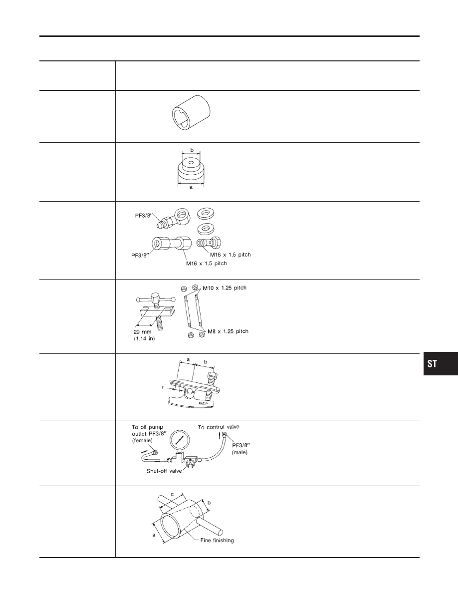
Special Service Tools
NCST0004
The actual shapes of Kent-Moore tools may differ from those of special service tools illustrated here.
Tool number
(Kent-Moore No.)
Tool name
Description
KV48100700
(J26364)
Torque adapter
NT169
Measuring pinion rotating torque
ST35300000
(
—
)
Drift
NT073
Installing power steering oil pump oil seal
a: 59 mm (2.32 in) dia.
b: 45 mm (1.77 in) dia.
KV48102500
(J33914)
Pressure gauge adapter
NT542
Measuring oil pressure
ST27180001
(J41777)
Steering wheel puller
NT544
Removing steering wheel
HT72520000
(J25730-B)
Ball joint remover
NT546
Removing ball joint
a: 33 mm (1.30 in)
b: 50 mm (1.97 in)
r: R11.5 mm (0.453 in)
KV48103500
(J26357 and J26357-
10)
Pressure gauge
NT547
Measuring oil pressure
KV48104400
(
—
)
Rack seal ring reformer
NT550
Reforming teflon ring
a: 50 mm (1.97 in) dia.
b: 36 mm (1.42 in) dia.
c: 100 mm (3.94 in)
GI
MA
EM
LC
EC
FE
CL
MT
AT
AX
SU
BR
RS
BT
HA
SC
EL
IDX
PREPARATION
Special Service Tools
ST-3
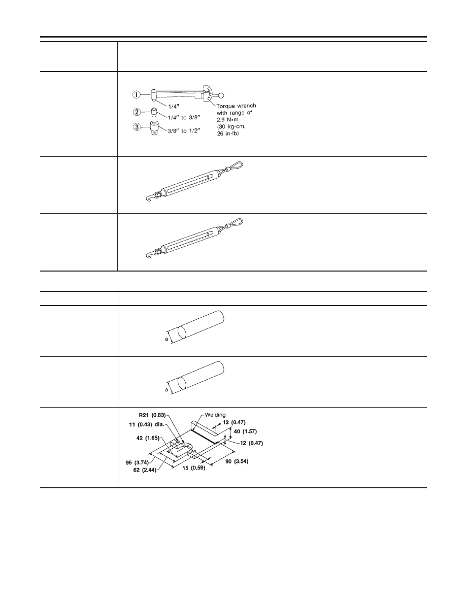
Tool number
(Kent-Moore No.)
Tool name
Description
ST3127S000
1 GG91030000
(See J25765-A)
Torque wrench
2 HT62940000
(
—
)
Socket adapter
3 HT62900000
(
—
)
Socket adapter
NT541
Measuring turning torque
(J-44372)
Spring gauge
NT127
Measuring steering wheel turning force
(J-44183-A)
Spring gauge
NT127
Measuring rack sliding force
Commercial Service Tools
NCST0005
Tool number
Description
Rear oil seal drift
NT063
Installing rear oil seal
a: 28 mm (1.10 in) dia.
Pinion oil seal drift
NT063
Installing pinion oil seal
a: 35 mm (1.38 in) dia.
Oil pump attachment
NT179
Disassembling and assembling oil pump
Unit: mm (in)
PREPARATION
Special Service Tools (Cont’d)
ST-4
Нет комментариевНе стесняйтесь поделиться с нами вашим ценным мнением.
Текст