Infiniti G20 (P11). Manual — part 521
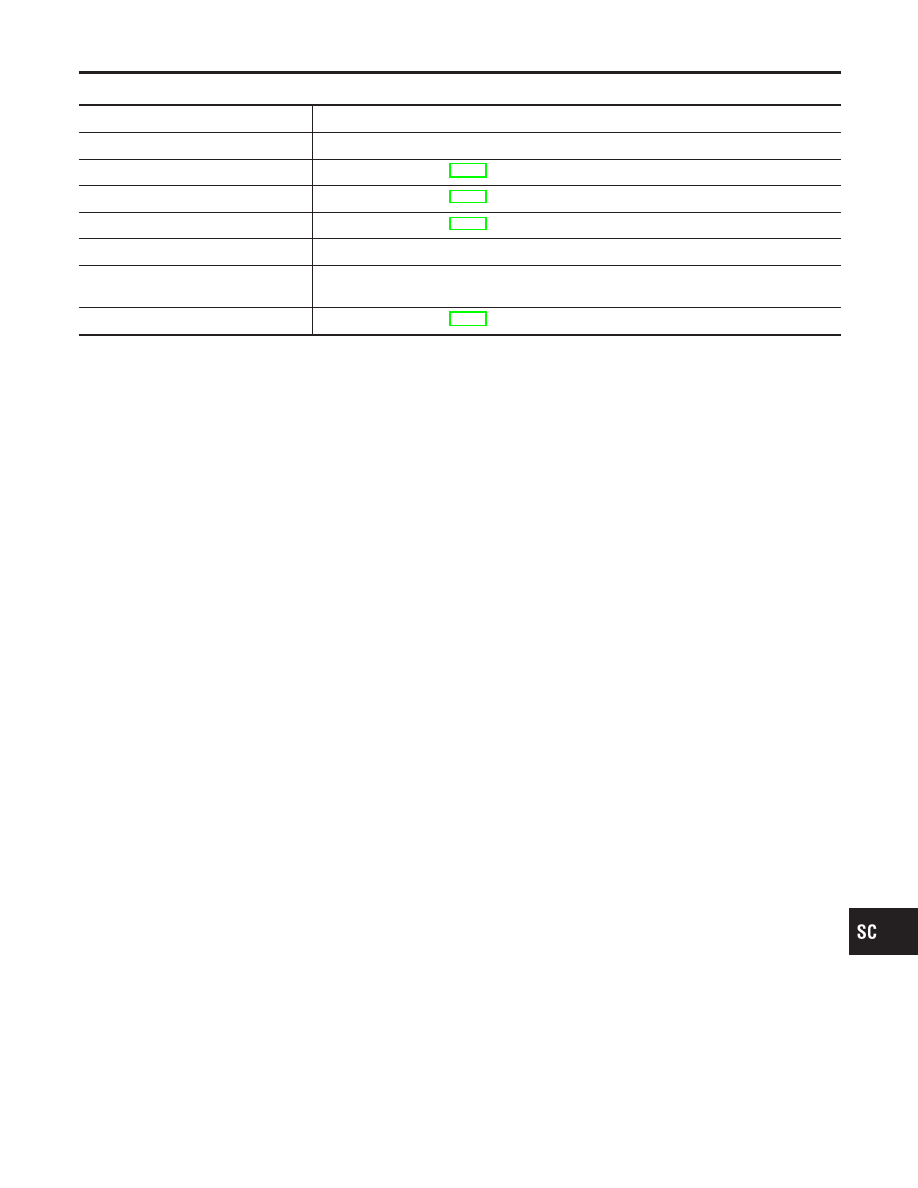
DIAGNOSTIC RESULT ITEM CHART
NCSC0020S01
Diagnostic item
Service procedure
CHARGING SYSTEM NORMAL
Charging system is normal and will also show DIODE RIPPLE test result.
NO CHARGING VOLTAGE
Go to “WORK FLOW”, SC-26.
LOW CHARGING VOLTAGE
Go to “WORK FLOW”, SC-26.
HIGH CHARGING VOLTAGE
Go to “WORK FLOW”, SC-26.
DIODE RIPPLE NORMAL
Diode ripple is OK and will also show CHARGING VOLTAGE test result.
EXCESS RIPPLE DETECTED
Replace the alternator. Perform “DIODE RIPPLE” test again using Battery/Starting/
Charging system tester to confirm repair.
DIODE RIPPLE NOT DETECTED
Go to “WORK FLOW”, SC-26.
GI
MA
EM
LC
EC
FE
CL
MT
AT
AX
SU
BR
ST
RS
BT
HA
EL
IDX
CHARGING SYSTEM
Trouble Diagnoses with Battery/Starting/Charging System Tester (Cont’d)
SC-25
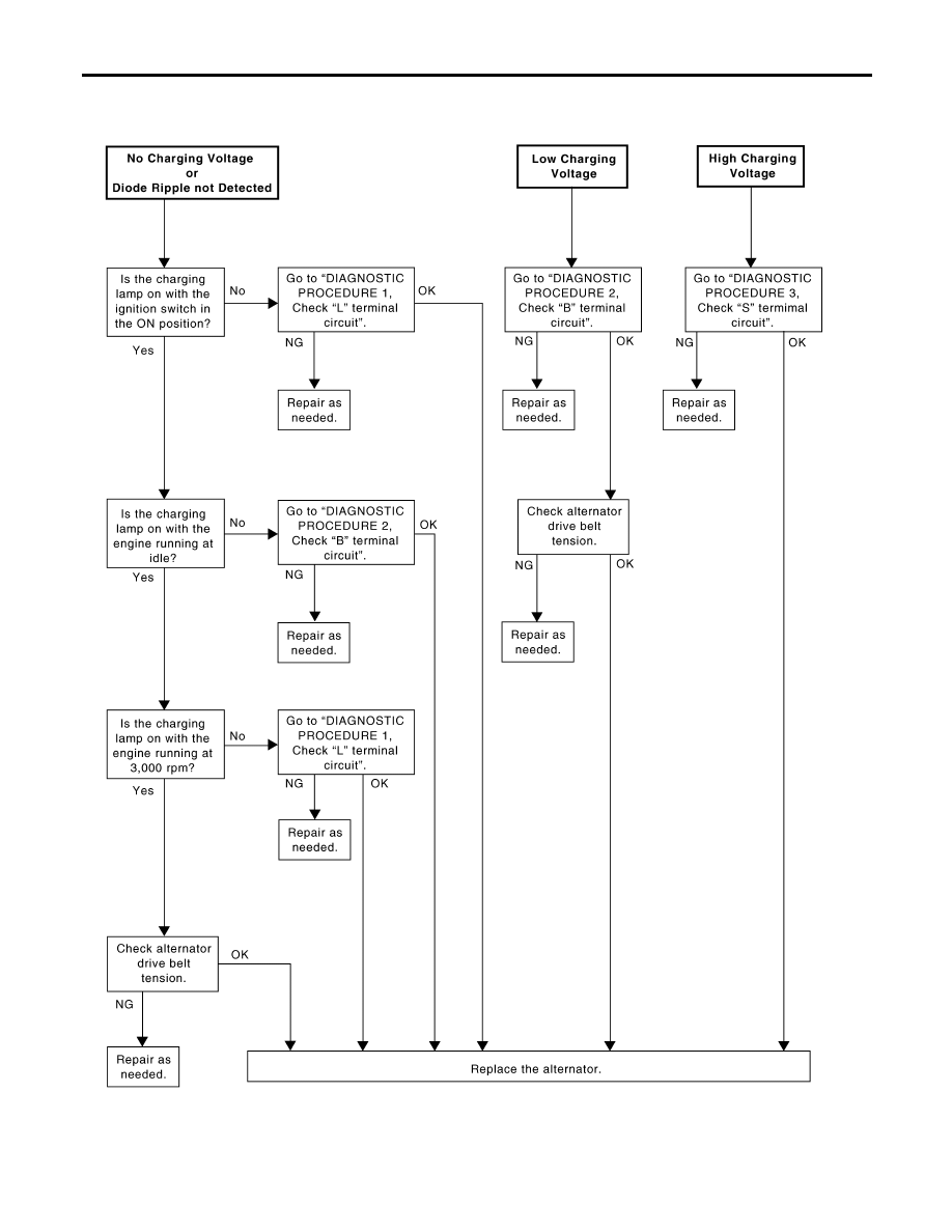
WORK FLOW
NCSC0020S02
SEL423X
CHARGING SYSTEM
Trouble Diagnoses with Battery/Starting/Charging System Tester (Cont’d)
SC-26
DIAGNOSTIC PROCEDURE 1
NCSC0020S03
Check “L” Terminal Circuit
NCSC0020S0301
1
CHECK “L” TERMINAL CONNECTION
Check to see if “L” terminal is clean and tight.
OK or NG
OK
©
GO TO 2.
NG
©
Repair “L” terminal connection. Confirm repair by performing complete Battery/Starting/
Charging system test.
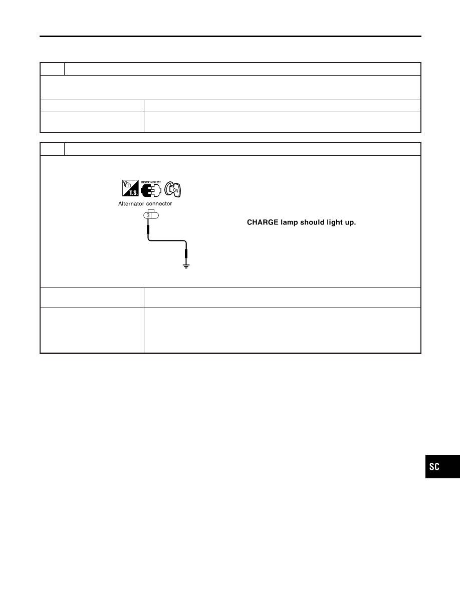
2
CHECK “L” TERMINAL CIRCUIT
1. Disconnect alternator connector.
2. Apply ground to alternator connector E106 terminal 3 (Y/R) with the ignition switch in the ON position.
SEL950X
OK or NG
OK
©
Replace the alternator. Confirm repair by performing complete Battery/Starting/Charging
system test.
NG
©
Check the following.
I
10A fuse [No. 11, located in fuse block (J/B)]
I
CHARGE lamp
I
Harness for open or short between combination meter and fuse
I
Harness for open or short between combination meter and alternator
GI
MA
EM
LC
EC
FE
CL
MT
AT
AX
SU
BR
ST
RS
BT
HA
EL
IDX
CHARGING SYSTEM
Trouble Diagnoses with Battery/Starting/Charging System Tester (Cont’d)
SC-27
DIAGNOSTIC PROCEDURE 2
=NCSC0020S04
Check “B” Terminal Circuit
NCSC0020S0401
1
CHECK “B” TERMINAL CONNECTION
Check to see if “B” terminal is clean and tight.
OK or NG
OK
©
GO TO 2. Confirm repair by performing complete Battery/Starting/Charging system test.
NG
©
Repair “B” terminal connection.
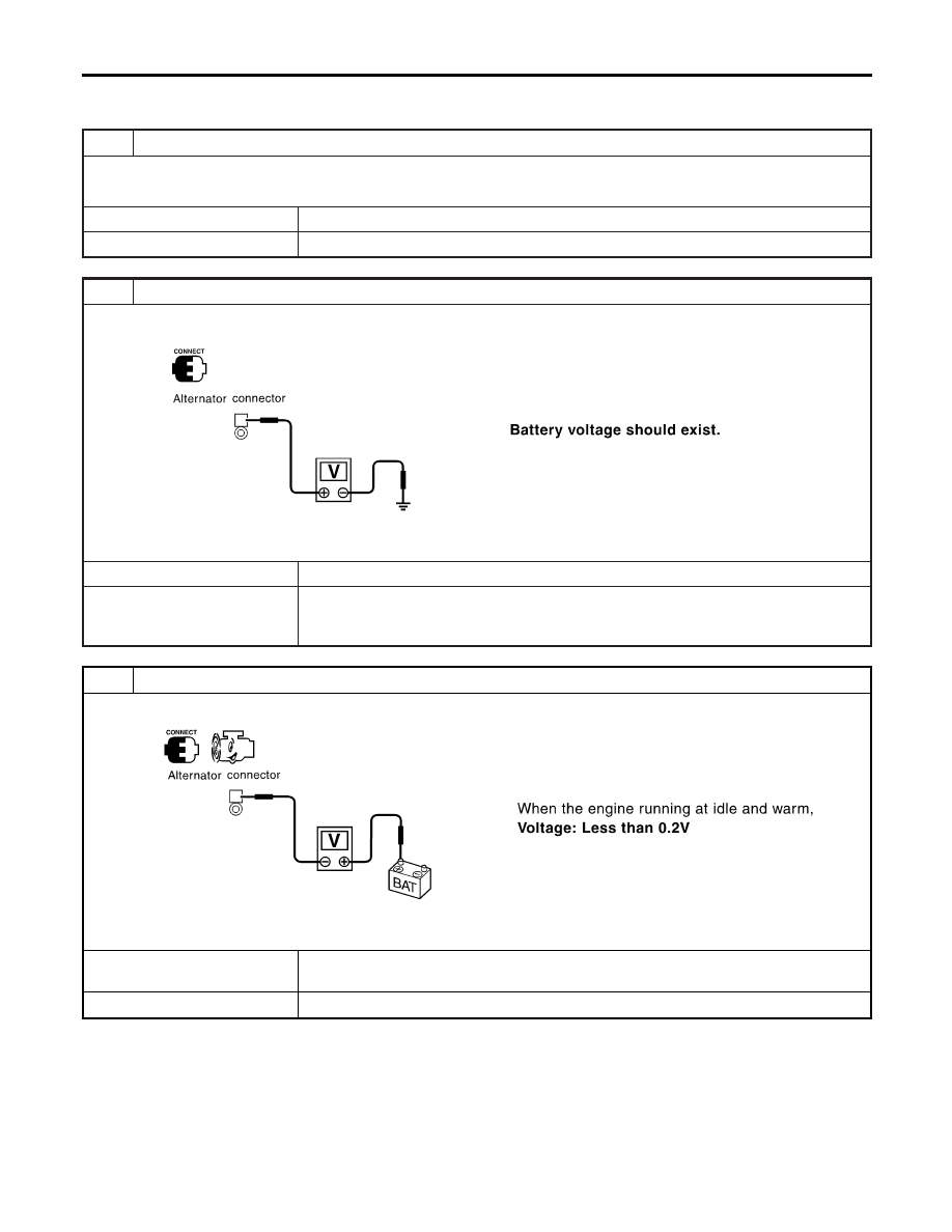
2
CHECK ALTERNATOR “B” TERMINAL CIRCUIT
Check voltage between alternator connector E107 terminal B (W) and ground using a digital circuit tester.
SEL951X
OK or NG
OK
©
GO TO 3.
NG
©
Check the following.
I
100A fusible link (letter e, located in fuse and fusible link box)
I
Harness for open or short between alternator and fusible link
3
CHECK “B” TERMINAL CONNECTION QUALITY (VOLTAGE DROP TEST)
Check voltage between alternator connector E107 terminal B (W) and battery positive terminal using a digital tester.
SEL952X
OK or NG
OK
©
Replace the alternator. Confirm repair by performing complete Battery/Starting/Charging
system test.
NG
©
Check harness between the battery and the alternator for poor continuity.
CHARGING SYSTEM
Trouble Diagnoses with Battery/Starting/Charging System Tester (Cont’d)
SC-28
Нет комментариевНе стесняйтесь поделиться с нами вашим ценным мнением.
Текст