Infiniti G20 (P11). Manual — part 207
Wiring Diagram
NCEC0150
TEC839
GI
MA
EM
LC
FE
CL
MT
AT
AX
SU
BR
ST
RS
BT
HA
SC
EL
IDX
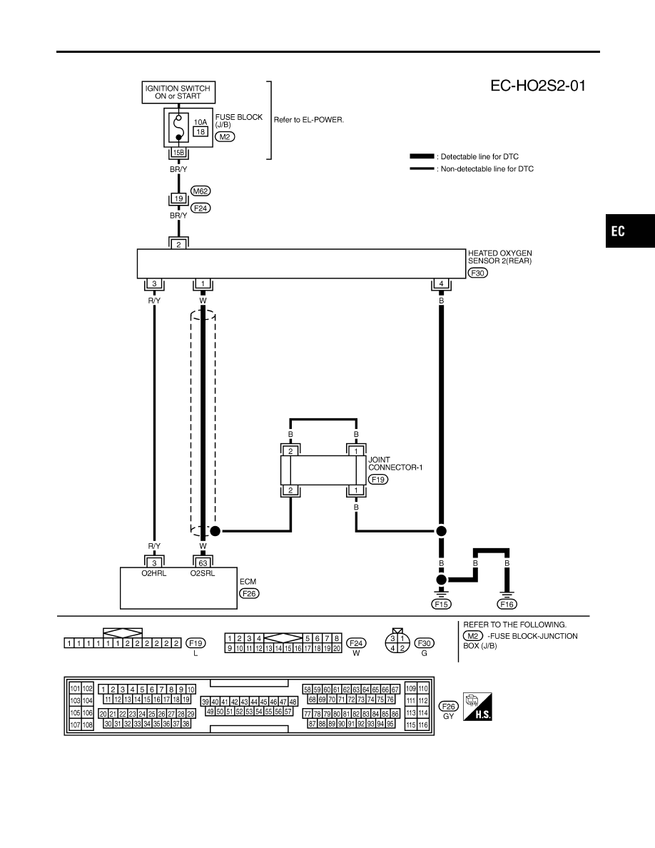
DTC P0137 HEATED OXYGEN SENSOR 2 (REAR) (MIN. VOLTAGE
MONITORING)
Wiring Diagram
EC-239
Diagnostic Procedure
NCEC0151
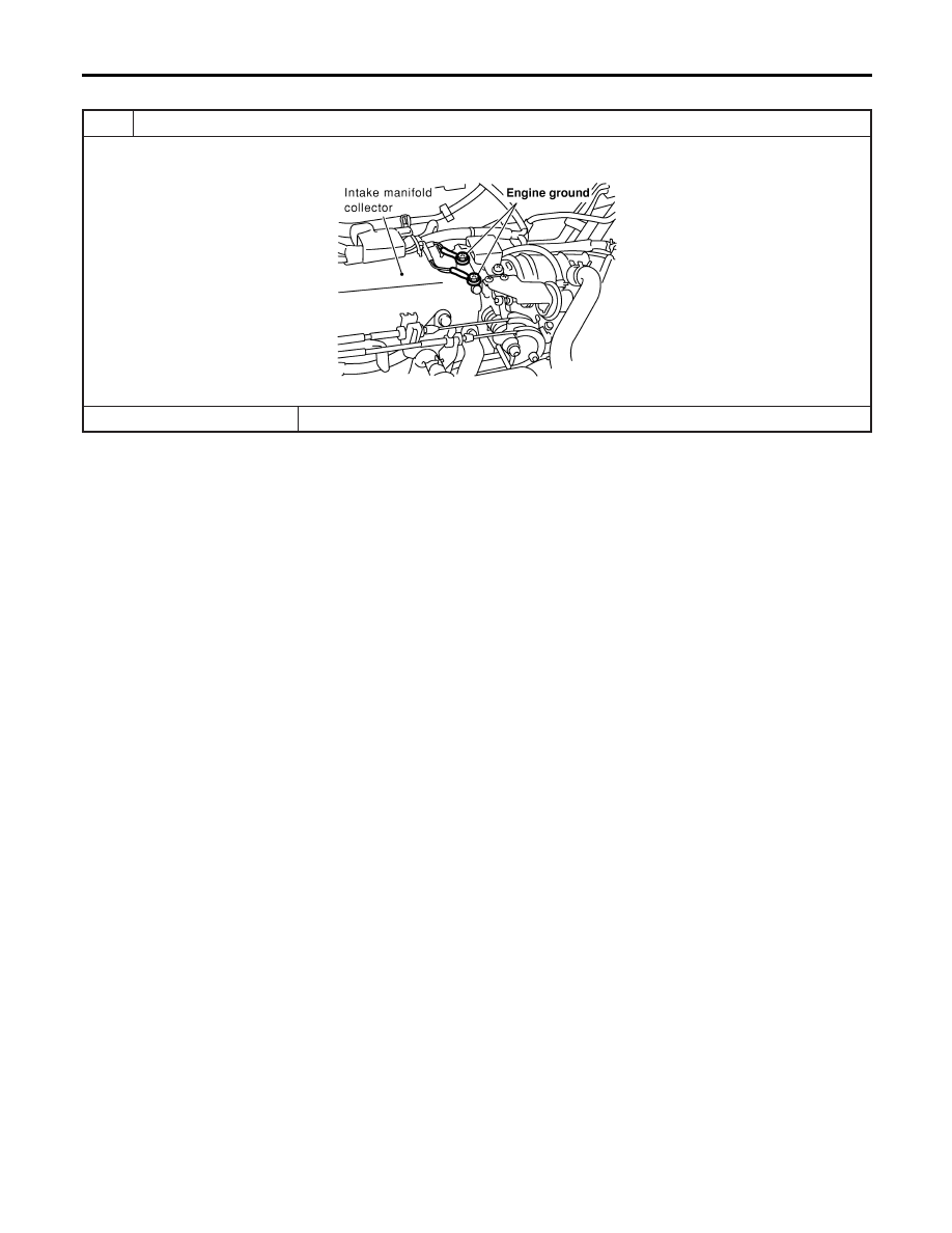
1
RETIGHTEN GROUND SCREWS
1. Turn ignition switch “OFF”.
2. Loosen and retighten engine ground screws.
SEF839X
©
GO TO 2.
DTC P0137 HEATED OXYGEN SENSOR 2 (REAR) (MIN. VOLTAGE
MONITORING)
Diagnostic Procedure
EC-240
2
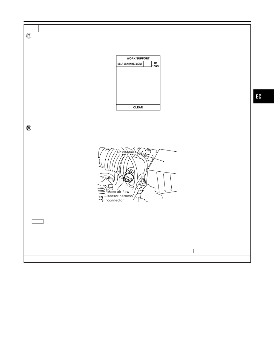
CLEAR THE SELF-LEARNING DATA
With CONSULT-II
1. Start engine and warm it up to normal operating temperature.
2. Select “SELF-LEARNING CONT” in “WORK SUPPORT” mode with CONSULT-II.
3. Clear the self-learning control coefficient by touching “CLEAR”.
SEF215Z
4. Run engine for at least 10 minutes at idle speed.
Is the 1st trip DTC P0172 detected? Is it difficult to start engine?
Without CONSULT-II
1. Start engine and warm it up to normal operating temperature.
2. Turn ignition switch “OFF”.
3. Disconnect mass air flow sensor harness connector, and restart and run engine for at least 3 seconds at idle speed.
SEF840X
4. Stop engine and reconnect mass air flow sensor harness connector.
5. Make sure 1st trip DTC P0100 is displayed.
6. Erase the 1st trip DTC memory. Refer to “HOW TO ERASE EMISSION-RELATED DIAGNOSTIC INFORMATION”,
7. Make sure DTC P0000 is displayed.
8. Run engine for at least 10 minutes at idle speed.
Is the 1st trip DTC P0172 detected? Is it difficult to start engine?
Yes or No
Yes
©
Perform trouble diagnosis for DTC P0172. Refer to EC-279.
No
©
GO TO 3.
GI
MA
EM
LC
FE
CL
MT
AT
AX
SU
BR
ST
RS
BT
HA
SC
EL
IDX
DTC P0137 HEATED OXYGEN SENSOR 2 (REAR) (MIN. VOLTAGE
MONITORING)
Diagnostic Procedure (Cont’d)
EC-241
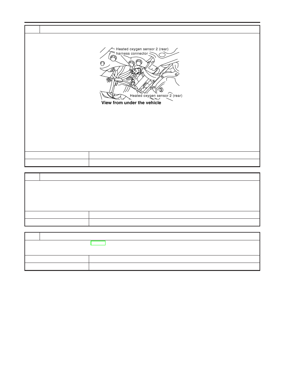
3
CHECK INPUT SIGNAL CIRCUIT
1. Turn ignition switch “OFF”.
2. Disconnect heated oxygen sensor 2 (rear) harness connector and ECM harness connector.
SEF918Z
3. Check harness continuity between ECM terminal 63 and HO2S2 terminal 1.
Refer to Wiring Diagram.
Continuity should exist.
4. Check harness continuity between ECM terminal 63 (or HO2S2 terminal 1) and ground.
Refer to Wiring Diagram.
Continuity should not exist.
5. Also check harness for short to ground and short to power.
OK or NG
OK
©
GO TO 4.
NG
©
Repair open circuit or short to ground or short to power in harness or connectors.
4
CHECK GROUND CIRCUIT
1. Check harness continuity between HO2S2 terminal 4 and body ground.
Refer to Wiring Diagram.
Continuity should exist.
2. Also check harness for short to power.
OK or NG
OK
©
GO TO 5.
NG
©
Repair open circuit or short to power in harness or connectors.
5
CHECK HEATED OXYGEN SENSOR 2 (REAR)
Refer to “Component Inspection”, EC-243.
OK or NG
OK
©
GO TO 6.
NG
©
Replace heated oxygen sensor 2 (rear).
DTC P0137 HEATED OXYGEN SENSOR 2 (REAR) (MIN. VOLTAGE
MONITORING)
Diagnostic Procedure (Cont’d)
EC-242
Нет комментариевНе стесняйтесь поделиться с нами вашим ценным мнением.
Текст