Infiniti G20 (P11). Manual — part 318
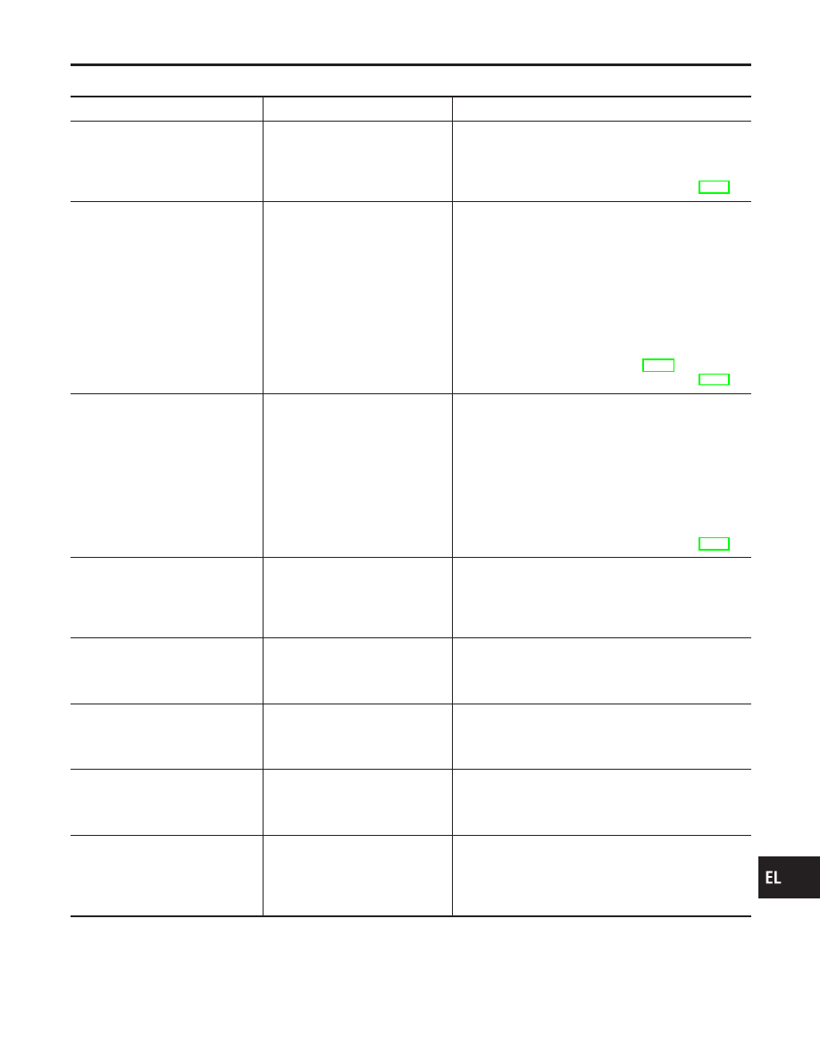
Trouble Diagnoses
NCEL0021
Symptom
Possible cause
Repair order
Neither headlamp operates.
1. 10A fuse
2. Lighting switch
3. Headlamp battery saver control
unit
1. Check 10A fuse [No. 24, located in fuse block (J/B)].
Verify battery positive voltage is present at terminal
7 of headlamp battery saver control unit.
2. Check lighting switch.
3. Check headlamp battery saver control unit. (EL-37)
LH headlamp (low and high beam)
does not operate, but RH head-
lamp (low and high beam) does
operate.
1. 15A fuse
2. Headlamp LH relay
3. Headlamp LH relay circuit
4. LH headlamp ground circuit
5. Lighting switch
6. Daytime light control unit
7. Headlamp battery saver control
unit
1. Check 15A fuse (No. 32, located in fusible link and
fuse box). Verify battery positive voltage is present
at terminals 1 and 3 of headlamp LH relay.
2. Check headlamp LH relay.
3. Check the following.
a. Headlamp LH relay and lighting switch.
b. Headlamp LH relay and headlamp battery saver
control unit.
4. Check harness between LH headlamp and daytime
light control unit.
5. Check lighting switch.
6. Check daytime light control unit. (EL-50)
7. Check headlamp battery saver control unit. (EL-37)
RH headlamp (low and high beam)
does not operate, but LH head-
lamp (low and high beam) does
operate.
1. 15A fuse
2. Headlamp RH relay
3. Headlamp RH relay circuit
4. RH headlamp ground circuit
5. Lighting switch
6. Headlamp battery saver control
unit
1. Check 15A fuse (No. 33, located in fusible link and
fuse box). Verify battery positive voltage is present
at terminals 1 and 3 of headlamp RH relay.
2. Check headlamp RH relay.
3. Check the following.
a. Headlamp RH relay and lighting switch.
b. Headlamp RH relay and headlamp battery saver
control unit.
4. Check harness between RH headlamp and ground.
5. Check lighting switch.
6. Check headlamp battery saver control unit. (EL-37)
LH high beam does not operate,
but LH low beam does operate.
1. Bulb
2. Open in LH low beams circuit
3. Lighting switch
1. Check bulb.
2. Check the following.
a. Lighting switch and daytime light control unit.
b. Daytime light control unit and LH headlamp.
3. Check lighting switch.
LH low beam does not operate, but
LH high beam does operate.
1. Bulb
2. Open in LH low beams circuit
3. Lighting switch
1. Check bulb.
2. Check harness between lighting switch and LH
headlamp.
3. Check lighting switch.
RH high beam does not operate,
but RH low beam does operate.
1. Bulb
2. Open in RH low beams circuit
3. Lighting switch
1. Check bulb.
2. Check harness between lighting switch and RH
headlamp.
3. Check lighting switch.
RH low beam does not operate,
but RH high beam does operate.
1. Bulb
2. Open in RH low beams circuit
3. Lighting switch
1. Check bulb.
2. Check harness between lighting switch and RH
headlamp.
3. Check lighting switch.
High beam indicator does not
work.
1. Bulb
2. Ground circuit
3. Open in high beam circuit
1. Check bulb in combination meter.
2. Check harness between high beam indicator and
ground.
3. Check harness between lighting switch and combi-
nation meter.
GI
MA
EM
LC
EC
FE
CL
MT
AT
AX
SU
BR
ST
RS
BT
HA
SC
IDX
HEADLAMP (FOR CANADA) — DAYTIME LIGHT SYSTEM —
Trouble Diagnoses
EL-49
Symptom
Possible cause
Repair order
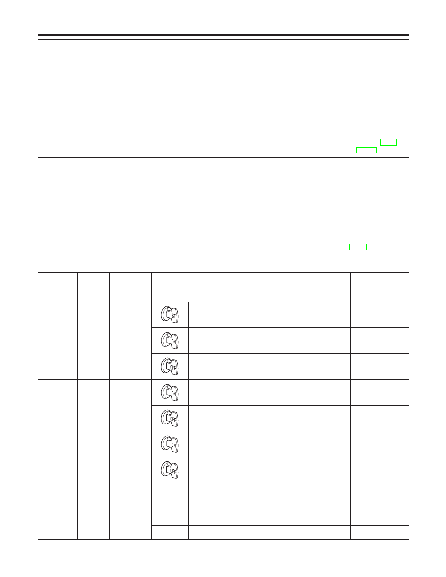
Battery saver control does not
operate properly.
1. RAP signal circuit
2. Driver or passenger side door
switch circuit
3. Lighting switch circuit
4. Headlamp battery saver control
unit
5. Smart entrance control unit
1. Check harness between headlamp battery saver
control unit terminal 10 and smart entrance control
unit terminal 5 for open or short circuit.
2. Check the following.
a. Smart entrance control unit and driver or passenger
side door switch for open or short circuit.
b. Driver or passenger side door switch ground circuit.
c. Driver or passenger side door switch.
3. Check harness between headlamp battery saver
control unit terminals 5 or 13 and lighting switch ter-
minal 12 and ground.
4. Check headlamp battery saver control unit. (EL-37)
5. Check smart entrance control unit. (EL-246)
Daytime light control does not
operate properly.
1. Bulb
2. Fuse check
3. Parking brake switch
4. Parking brake switch circuit
5. Daytime light control unit
1. Check bulb.
2. Check the following.
a. 10A fuse [No. 11, located in fuse block (J/B)]. Verify
battery positive voltage is present at terminal 11 of
daytime light control unit.
b. 10A fuse [No. 26, located in fuse block (J/B)]. Verify
battery positive voltage is present at terminal 1 of
daytime light control unit.
3. Check parking brake switch.
4. Check harness between parking brake switch and
daytime light control unit.
5. Check daytime light control unit. (EL-50)
DAYTIME LIGHT CONTROL UNIT INSPECTION TABLE
NCEL0021S01
Terminal
No.
Wire
color
Item
Condition
Voltage
(Approximate val-
ues)
1
B/Y
Start signal
When turning ignition switch to “ST”
Battery voltage
When turning ignition switch to “ON” from “ST”
Less than 1V
When turning ignition switch to “OFF”
Less than 1V
2
R
Power
source
When turning ignition switch to “ON”
Battery voltage
When turning ignition switch to “OFF”
Battery voltage
3
R/W
Power
source
When turning ignition switch to “ON”
Battery voltage
When turning ignition switch to “OFF”
Battery voltage
4
P/L
Lighting
switch (Low
beam)
When lighting switch is turned to the 2ND position with
“LOW BEAM” position
Battery voltage
5
R/B
Lighting
switch (High
beam)
When turning lighting switch to “HIGH BEAM”
Battery voltage
When turning lighting switch to “FLASH TO PASS”
Battery voltage
HEADLAMP (FOR CANADA) — DAYTIME LIGHT SYSTEM —
Trouble Diagnoses (Cont’d)
EL-50
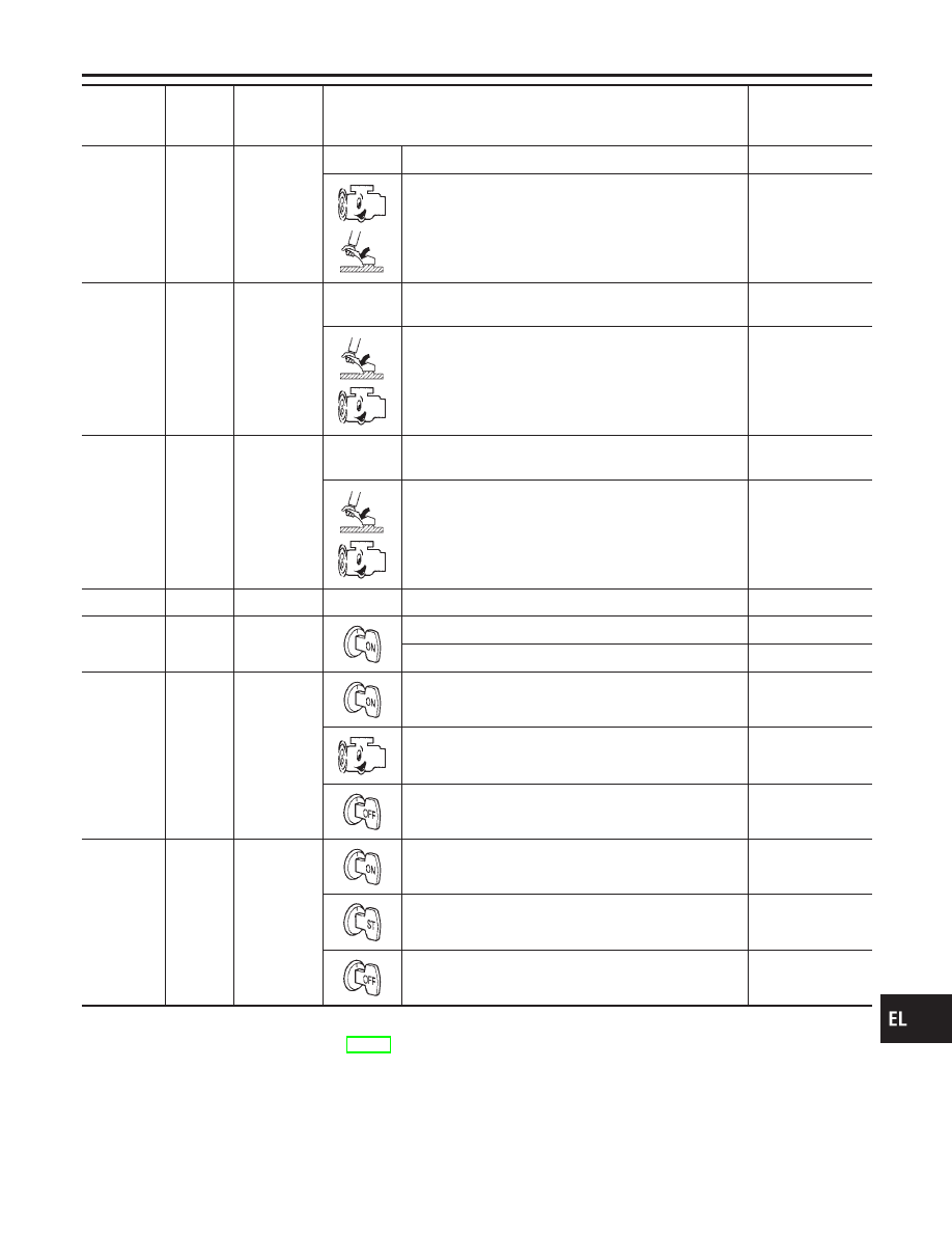
Terminal
No.
Wire
color
Item
Condition
Voltage
(Approximate val-
ues)
6
OR/L
High beam
LH
When turning lighting switch to “HIGH BEAM”
Battery voltage
When releasing parking brake with engine running and
turning lighting switch to “OFF” (daytime light operation)
CAUTION:
Block wheels and ensure selector lever is in N or P
position.
Approx. half bat-
tery voltage
7
OR/B
Headlamp
LH control
(ground)
When lighting switch is turned to the 2ND position with
“LOW BEAM” position
Less than 1V
When releasing parking brake with engine running and
turning lighting switch to “OFF” (daytime light operation)
CAUTION:
Block wheels and ensure selector lever is in N or P
position.
Approx. half bat-
tery voltage
8
R/G
High beam
RH
When lighting switch is turned to the 2ND position with
“HIGH BEAM” position
Battery voltage
When releasing parking brake with engine running and
turning lighting switch to “OFF” (daytime light operation)
CAUTION:
Block wheels and ensure selector lever is in N or P
position.
Approx. half bat-
tery voltage
9
B
Ground
—
—
10
Y/B
Parking
brake switch
When parking brake is released
Battery voltage
When parking brake is set
Less than 1.5V
11
Y/R
Alternator
When turning ignition switch to “ON”
Less than 1V
When engine is running
Battery voltage
When turning ignition switch to “OFF”
Less than 1V
12
LG/B
Power
source
When turning ignition switch to “ON”
Battery voltage
When turning ignition switch to “ST”
Battery voltage
When turning ignition switch to “OFF”
Less than 1V
BATTERY SAVER CONTROL UNIT INSPECTION TABLE
NCEL0021S02
Refer to “HEADLAMP (FOR USA)” (EL-37).
GI
MA
EM
LC
EC
FE
CL
MT
AT
AX
SU
BR
ST
RS
BT
HA
SC
IDX
HEADLAMP (FOR CANADA) — DAYTIME LIGHT SYSTEM —
Trouble Diagnoses (Cont’d)
EL-51
Нет комментариевНе стесняйтесь поделиться с нами вашим ценным мнением.
Текст