Infiniti G20 (P11). Manual — part 316
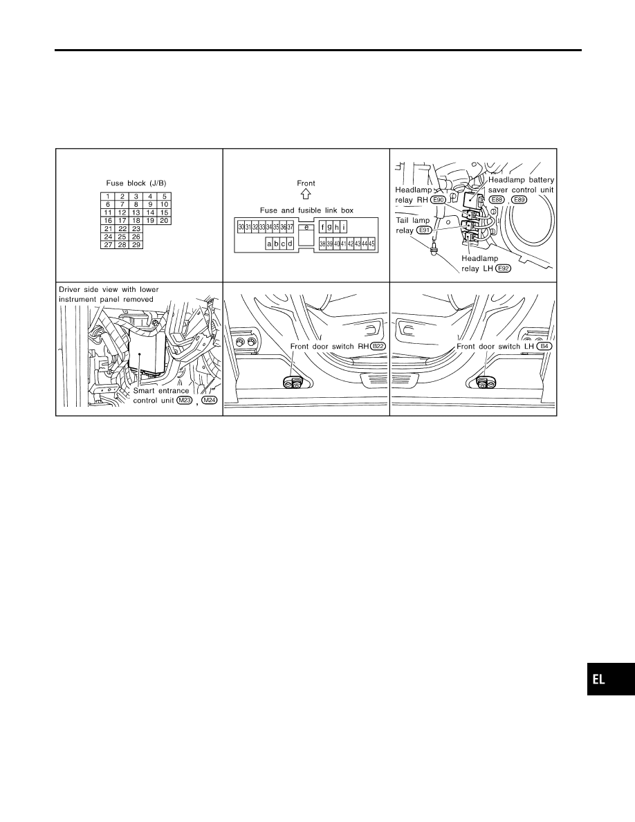
Component Parts and Harness Connector
Location
NCEL0166
SEL665W
System Description
NCEL0017
The headlamp system for Canada vehicles contains a daytime light control unit that activates the high beam
headlamps at approximately half illumination whenever the engine is running. If the parking brake is applied
before the engine is started the daytime lights will not be illuminated. The daytime lights will illuminate once
the parking brake is released. Thereafter, the daytime lights will continue to operate when the parking brake
is applied.
And battery saver system is controlled by the headlamp battery saver control unit and smart entrance control
unit.
Power is supplied at all times
I
to daytime light control unit terminal 3, and
I
to headlamp LH relay terminals 1 and 3
I
through 15A fuse (No. 32, located in the fuse and fusible link box), and
I
to daytime light control unit terminal 2 and
I
to headlamp RH relay terminals 1 and 3
I
through 15A fuse (No. 33, located in the fuse and fusible link box), and
I
to headlamp battery saver control unit terminal 7
I
through 10A fuse [No. 24, located in the fuse block (J/B)].
Ground is supplied
I
to daytime light control unit terminal 9 and
I
to headlamp battery saver control unit terminals 4 and 11
When the ignition switch is in the ON or START position, power is also supplied
GI
MA
EM
LC
EC
FE
CL
MT
AT
AX
SU
BR
ST
RS
BT
HA
SC
IDX
HEADLAMP (FOR CANADA) — DAYTIME LIGHT SYSTEM —
Component Parts and Harness Connector Location
EL-41
I
to daytime light control unit terminal 12,
I
to headlamp battery saver control unit terminal 10, and
I
to smart entrance control unit terminal 33
I
through 10A fuse [No. 8, located in the fuse block (J/B)], and
I
to headlamp battery saver control unit terminal 1
I
through 10A fuse [No. 16, located in the fuse block (J/B)].
When the ignition switch is in the START position, power is supplied
I
to daytime light control unit terminal 1
I
through 10A fuse [No. 26, located in the fuse block (J/B)].
HEADLAMP OPERATION
NCEL0017S01
When Ignition Switch is in ON or START Position
NCEL0017S0103
Ground is supplied
I
to headlamp LH relay terminal 2 from headlamp battery saver control unit terminal 8
I
through headlamp battery saver control unit terminal 9, and
I
through body grounds E9 and E28, and
I
to headlamp RH relay terminal 2 from headlamp battery saver control unit terminal 2
I
through headlamp battery saver control unit terminal 3, and
I
through body grounds E9 and E28.
Headlamp relays (LH and RH) are then energized.
When Ignition Switch is in OFF or ACC Position
NCEL0017S0104
When lighting switch is in 1ST (or 2ND) position, ground is supplied
I
to headlamp battery saver control unit terminals 5 and 13
I
from lighting switch terminal 11.
And then, ground is also supplied to headlamp LH and RH relays terminal 2 from headlamp battery saver
control unit. Headlamp relays (LH and RH) are then energized.
Low Beam Operation
NCEL0017S0101
When the lighting switch is turned to the 2ND position and placed in LOW (“B”) position, power is supplied
I
from lighting switch terminal 7
I
to RH headlamp terminal 3
I
to daytime light control unit terminal 4.
Ground is supplied to RH headlamp terminal 2 through body grounds E9 and E28.
Also, when the lighting switch is turned to the 2ND position and placed in LOW (“B”) position, power is sup-
plied
I
from lighting switch terminal 10
I
to LH headlamp terminal 3.
Ground is supplied
I
to LH headlamp terminal 2
I
from daytime light control unit terminal 7
I
through daytime light control unit terminal 9
I
through body grounds E9 and E28.
With power and ground supplied, the low beam headlamps illuminate.
High Beam Operation/Flash-to-pass Operation
NCEL0017S0102
When the lighting switch is turned to the 2ND position and placed in HIGH (“A”) position, power is supplied
I
from lighting switch terminal 6
I
to terminal 1 of RH headlamp.
When the lighting switch is turned to the 2ND position and placed in HIGH (“A”) position, power is supplied
I
from lighting switch terminal 9
I
to daytime light control terminal 5
I
to combination meter terminal 26 for the high beam indicator, and
I
through daytime light control terminal 6
HEADLAMP (FOR CANADA) — DAYTIME LIGHT SYSTEM —
System Description (Cont’d)
EL-42
I
to terminal 1 of LH headlamp.
Ground is supplied in the same manner as low beam operation.
Ground is supplied to terminal 27 of the combination meter through body grounds M15, M71 and M76.
With power and ground supplied, the high beam headlamps and HI BEAM indicator illuminate.
BATTERY SAVER CONTROL
NCEL0017S04
When the ignition switch is turned from ON (or START) to OFF (or ACC) positions while headlamps are
illuminated, The RAP signal is supplied to terminal 10 of the headlamp battery saver control unit from smart
entrance control unit terminal 5.
After counting 45 seconds by the RAP signal from the smart entrance control unit to headlamp battery saver
control unit, the ground supply to terminal 1 of headlamp LH and RH relays from headlamp battery saver con-
trol unit terminals 2 and 8 is terminated.
Then headlamps are turned off.
The headlamps are turned off when driver or passenger side door is opened even if 45 seconds have not
passed after the ignition switch is turned from ON (or START) to OFF (or ACC) positions while headlamps are
illuminated.
When the lighting switch is turned from OFF to 2ND after headlamps are turned to off by the battery saver
control, ground is supply
I
to headlamp battery saver control unit terminals 5 and 13 from lighting switch terminal 11, and
I
to headlamp LH and RH relays terminal 2 from headlamp battery saver control unit terminals 2 and 8.
Then headlamps illuminate again.
DAYTIME LIGHT OPERATION
NCEL0017S02
With the engine running, the lighting switch in the OFF or 1ST position and parking brake released, power is
supplied
I
through daytime light control unit terminal 6
I
to terminal 1 of LH headlamp, and
I
through terminal 2 of LH headlamp
I
to daytime light control unit terminal 7, and
I
through daytime light control unit terminal 8
I
to terminal 1 of RH headlamp.
Ground is supplied to terminal 2 of RH headlamp through body grounds E9 and E28.
Because the high beam headlamps are now wired in series, they operate at half illumination.
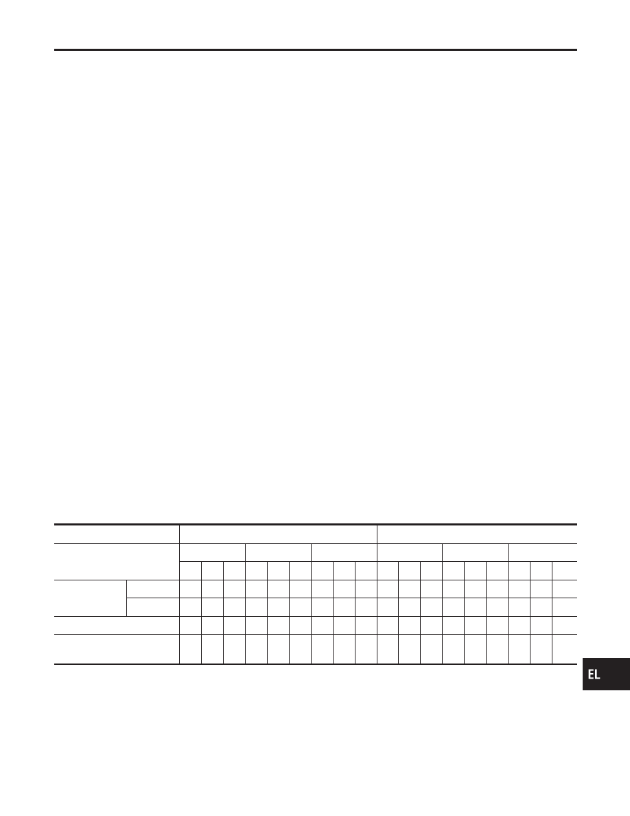
OPERATION
NCEL0017S03
After starting the engine with the lighting switch in the “OFF” or “1ST” position, the headlamp high beam auto-
matically turns on. Lighting switch operations other than the above are the same as conventional light sys-
tems.
Engine
With engine stopped
With engine running
Lighting switch
OFF
1ST
2ND
OFF
1ST
2ND
A
B
C
A
B
C
A
B
C
A
B
C
A
B
C
A
B
C
Headlamp
High beam
X
X
O
X
X
O
O
X
O
g
*
g
*
O
g
*
g
*
O
O
X
O
Low beam
X
X
X
X
X
X
X
O
X
X
X
X
X
X
X
X
O
X
Clearance and tail lamp
X
X
X
O
O
O
O
O
O
X
X
X
O
O
O
O
O
O
License and instrument illu-
mination lamp
X
X
X
O
O
O
O
O
O
X
X
X
O
O
O
O
O
O
A: “HIGH BEAM” position
B: “LOW BEAM” position
C: “FLASH TO PASS” position
O : Lamp “ON”
X : Lamp “OFF”
g
: Lamp dims. (Added functions)
*: When starting the engine with the parking brake released, the daytime light will come ON.
When starting the engine with the parking brake pulled, the daytime light won’t come ON.
GI
MA
EM
LC
EC
FE
CL
MT
AT
AX
SU
BR
ST
RS
BT
HA
SC
IDX
HEADLAMP (FOR CANADA) — DAYTIME LIGHT SYSTEM —
System Description (Cont’d)
EL-43
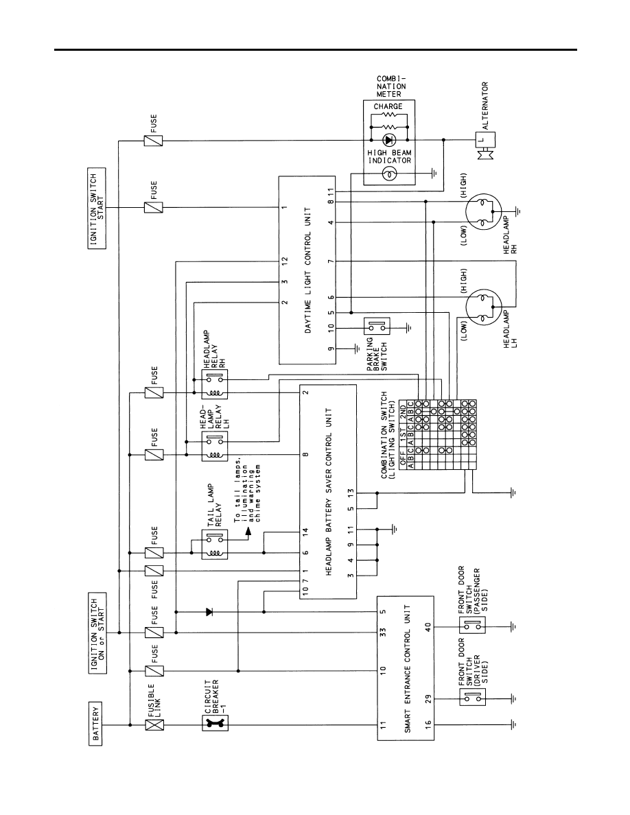
Schematic
NCEL0167
TEL864B
HEADLAMP (FOR CANADA) — DAYTIME LIGHT SYSTEM —
Schematic
EL-44
Нет комментариевНе стесняйтесь поделиться с нами вашим ценным мнением.
Текст