Infiniti G20 (P11). Manual — part 356
2
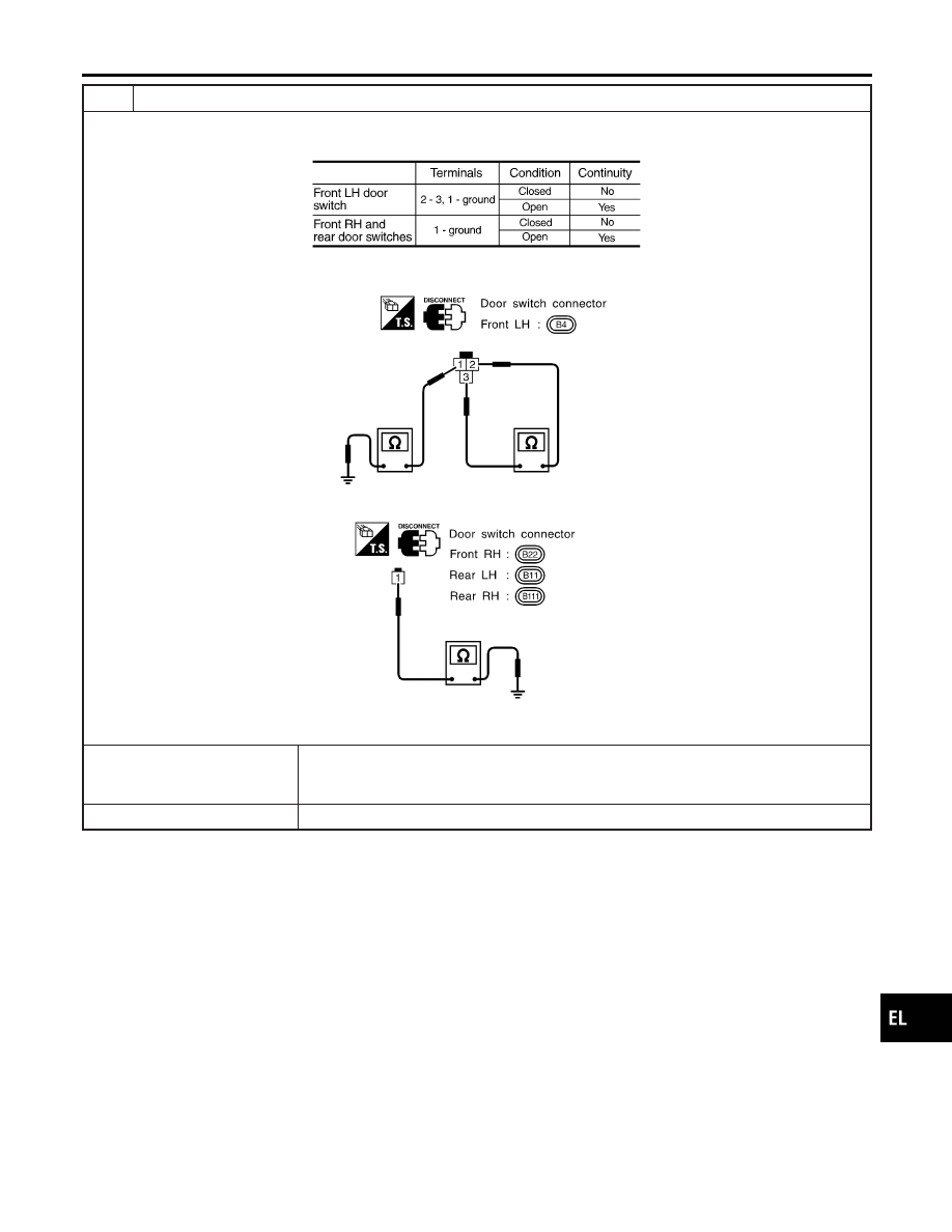
CHECK DOOR SWITCH
1. Disconnect door switch connector.
2. Check continuity between door switch terminals.
MTBL0384
SEL887VA
OK or NG
OK
©
Check the following.
I
Door switch ground circuit (Front) or door switch ground condition
I
Harness for open or short between control unit and door switch
NG
©
Replace door switch.
GI
MA
EM
LC
EC
FE
CL
MT
AT
AX
SU
BR
ST
RS
BT
HA
SC
IDX
MULTI-REMOTE CONTROL SYSTEM
Trouble Diagnoses (Cont’d)
EL-201
KEY SWITCH (INSERT) CHECK
=NCEL0115S07
1
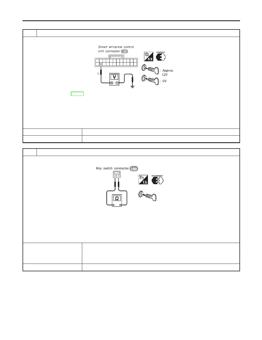
CHECK KEY SWITCH INPUT SIGNAL
Check voltage between smart entrance control unit terminal 32 and ground.
SEL888V
Refer to wiring diagram in EL-194.
Voltage [V]:
Condition of key switch: Key is inserted.
Approx. 12
Condition of key switch: Key is withdrawn.
0
OK or NG
OK
©
Key switch is OK.
NG
©
GO TO 2.
2
CHECK KEY SWITCH (INSERT)
Check continuity between terminals 1 and 2.
SEL784V
Continuity:
Condition of key switch: Key is inserted.
Yes
Condition of key switch: Key is withdrawn.
No
OK or NG
OK
©
Check the following.
I
10A fuse [No. 24, located in fuse block (J/B)]
I
Harness for open or short between key switch and fuse
I
Harness for open or short between smart entrance control unit and key switch
NG
©
Replace key switch.
MULTI-REMOTE CONTROL SYSTEM
Trouble Diagnoses (Cont’d)
EL-202
DOOR LOCK/UNLOCK SWITCH CHECK
=NCEL0115S12
1
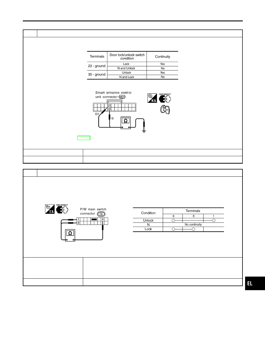
CHECK DOOR LOCK/UNLOCK SWITCH INPUT SIGNAL
1. Disconnect control unit connector.
2. Check continuity between control unit terminal 23 or 35 and ground.
MTBL0659
SEL875V
Refer to wiring diagram in EL-194.
OK or NG
OK
©
Door lock/unlock switch is OK.
NG
©
GO TO 2.
2
CHECK DOOR LOCK/UNLOCK SWITCH
1. Disconnect door lock/unlock switch connector.
2. Check continuity between each door lock/unlock switch terminals.
I
Power window main switch (Door lock/unlock switch)
SEL670W
OK or NG
OK
©
Check the following.
I
Ground circuit for door lock/unlock switch
I
Harness for open or short between door lock/unlock switch and smart entrance control
unit connector
NG
©
Replace door lock/unlock switch.
GI
MA
EM
LC
EC
FE
CL
MT
AT
AX
SU
BR
ST
RS
BT
HA
SC
IDX
MULTI-REMOTE CONTROL SYSTEM
Trouble Diagnoses (Cont’d)
EL-203
DOOR UNLOCK SENSOR CHECK
=NCEL0115S06
1
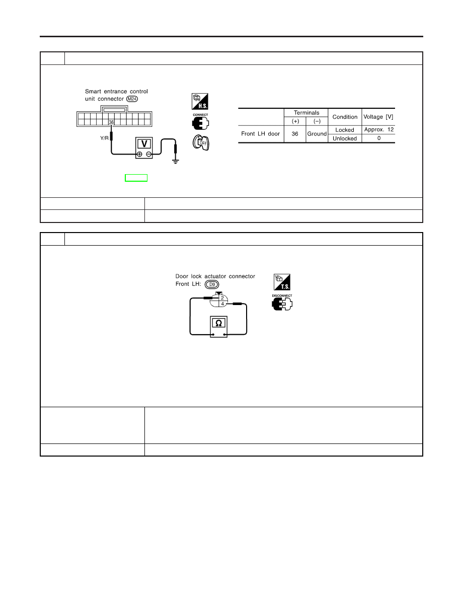
CHECK DOOR UNLOCK SENSOR INPUT SIGNAL
Check voltage between smart entrance control unit terminal 36 and ground.
SEL189X
Refer to wiring diagram in EL-194.
OK or NG
OK
©
Door unlock sensor (driver side) is OK.
NG
©
GO TO 2.
2
CHECK DOOR UNLOCK SENSOR
1. Disconnect door unlock sensor connector.
2. Check continuity between door unlock sensor (driver side) terminals.
SEL247VE
Continuity:
Condition: Locked
No
Condition: Unlocked
Yes
OK or NG
OK
©
Check the following.
I
Door unlock sensor ground circuit
I
Harness for open or short between smart entrance control unit and door unlock sensor
(driver side)
NG
©
Replace door unlock sensor (driver side).
MULTI-REMOTE CONTROL SYSTEM
Trouble Diagnoses (Cont’d)
EL-204
Нет комментариевНе стесняйтесь поделиться с нами вашим ценным мнением.
Текст