Infiniti G20 (P11). Manual — part 357
HAZARD REMINDER CHECK
=NCEL0115S08
1
CHECK HAZARD INDICATOR
Check if hazard indicator flashes with hazard switch.
Does hazard indicator operate?
Yes
©
GO TO 2.
No
©
Check “hazard indicator” circuit.
2
CHECK HAZARD REMINDER OPERATION
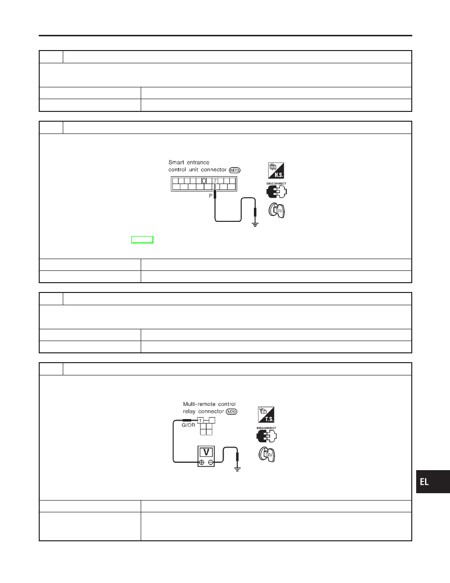
1. Disconnect smart entrance control unit connector.
2. Apply ground to control unit terminal 7.
SEL890V
Refer to wiring diagram in EL-195.
Does hazard indicator illuminate?
Yes
©
Replace smart entrance control unit.
No
©
GO TO 3.
3
CHECK MULTI-REMOTE CONTROL RELAY
Check multi-remote control relay.
OK or NG
OK
©
GO TO 4.
NG
©
Replace.
4
CHECK POWER SUPPLY FOR MULTI-REMOTE CONTROL RELAY
1. Disconnect multi-remote control relay connector.
2. Check voltage between terminal 1 and ground.
SEL244VB
Battery voltage should exist.
OK or NG
OK
©
GO TO 5.
NG
©
Check the following.
I
10A fuse [No. 20, located in fuse block (J/B)]
I
Harness for open or short between multi-remote control relay and fuse
GI
MA
EM
LC
EC
FE
CL
MT
AT
AX
SU
BR
ST
RS
BT
HA
SC
IDX
MULTI-REMOTE CONTROL SYSTEM
Trouble Diagnoses (Cont’d)
EL-205
5
CHECK MULTI-REMOTE CONTROL RELAY CIRCUIT
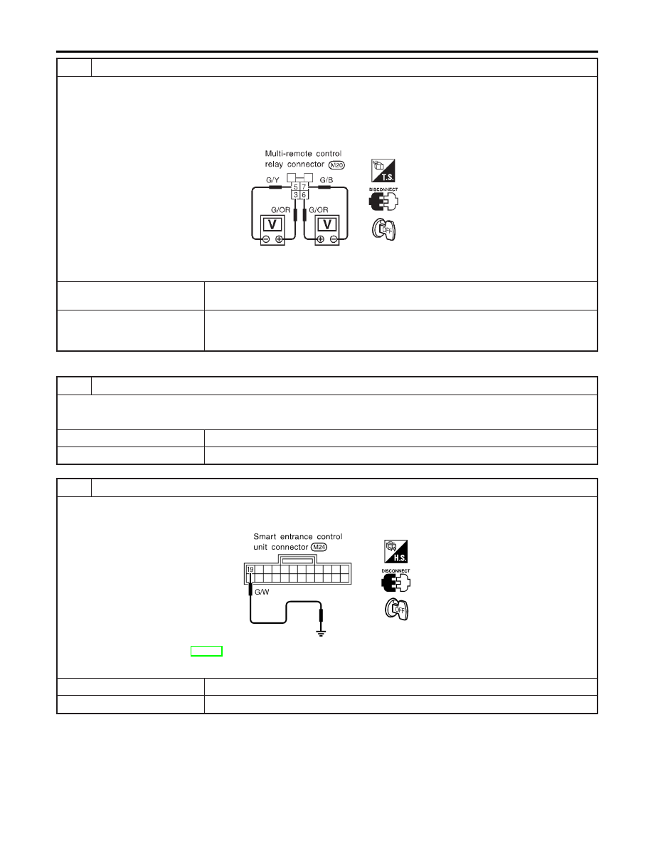
1. Disconnect multi-remote control relay connector.
2. Check voltage between terminals 3 and 5.
Battery voltage should exist.
3. Check voltage between terminals 6 and 7.
Battery voltage should exist.
SEL245VB
OK or NG
OK
©
Check harness for open or short between smart entrance control unit and multi-remote
control relay.
NG
©
Check the following.
I
Harness for open or short between smart entrance multi-remote control relay and fuse
I
Harness for open or short between multi-remote control relay and turn signal lamps
HORN REMINDER CHECK
NCEL0115S11
1
CHECK HORN
Check if horn sounds with horn switch.
Does horn operate?
Yes
©
GO TO 2.
No
©
Check horn circuit.
2
CHECK HORN REMINDER OPERATION
1. Disconnect smart entrance control unit connector.
2. Apply ground to smart entrance control unit terminal 19.
SEL075WA
Refer to wiring diagram in EL-196.
Does horn sound?
Yes
©
Replace smart entrance control unit.
No
©
Check harness for open or short between smart entrance control unit and horn relay.
MULTI-REMOTE CONTROL SYSTEM
Trouble Diagnoses (Cont’d)
EL-206
TRUNK LID OPENER CHECK
=NCEL0115S10
1
CHECK TRUNK LID OPENER OPERATION
Does trunk lid opener operate with trunk lid opener switch?
Yes or No
Yes
©
GO TO 2.
No
©
GO TO 3.
2
CHECK TRUNK LID OPENER CIRCUIT
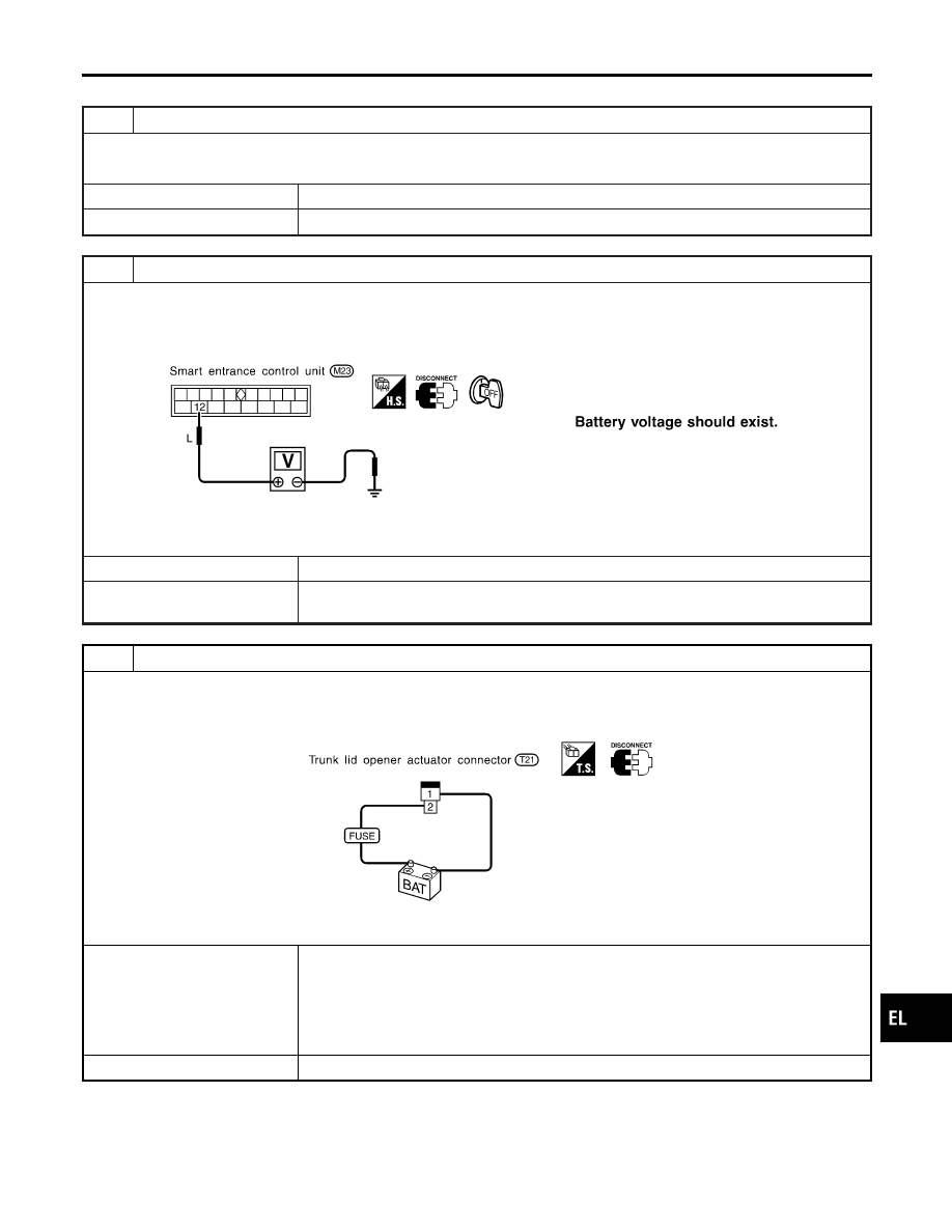
1. Disconnect smart entrance control unit connector.
2. Check voltage between smart entrance control unit connector terminal 12 and ground.
SEL675W
OK or NG
OK
©
Replace smart entrance control unit.
NG
©
Check harness or open or short between trunk lid opener relay and smart entrance con-
trol unit.
3
CHECK TRUNK LID OPENER ACTUATOR
1. Disconnect trunk lid opener actuator connector.
2. Check to see if trunk lid opens when 12V is applied between trunk lid opener actuator terminals 1 and 2.
SEL676W
OK or NG
OK
©
Check the following.
I
15A fuse [No. 15, located in the fuse block (J/B)]
I
Trunk lid opener relay
I
Harness for open or short between trunk lid opener relay and fuse
I
Harness for open or short between trunk lid opener relay and trunk lid opener actuator
I
Trunk lid opener actuator ground circuit
NG
©
Replace trunk lid opener actuator.
GI
MA
EM
LC
EC
FE
CL
MT
AT
AX
SU
BR
ST
RS
BT
HA
SC
IDX
MULTI-REMOTE CONTROL SYSTEM
Trouble Diagnoses (Cont’d)
EL-207
INTERIOR ROOM LAMP OPERATION CHECK
=NCEL0115S09
1
CHECK INTERIOR ROOM LAMP
Check if the interior room lamp switch is in the “ON” position and the lamp illuminates.
Does interior room lamp illuminate?
Yes
©
GO TO 2.
No
©
Check the following.
I
Harness for open or short between smart entrance control unit and interior room lamp
I
Interior room lamp
2
CHECK INTERIOR ROOM LAMP CIRCUIT
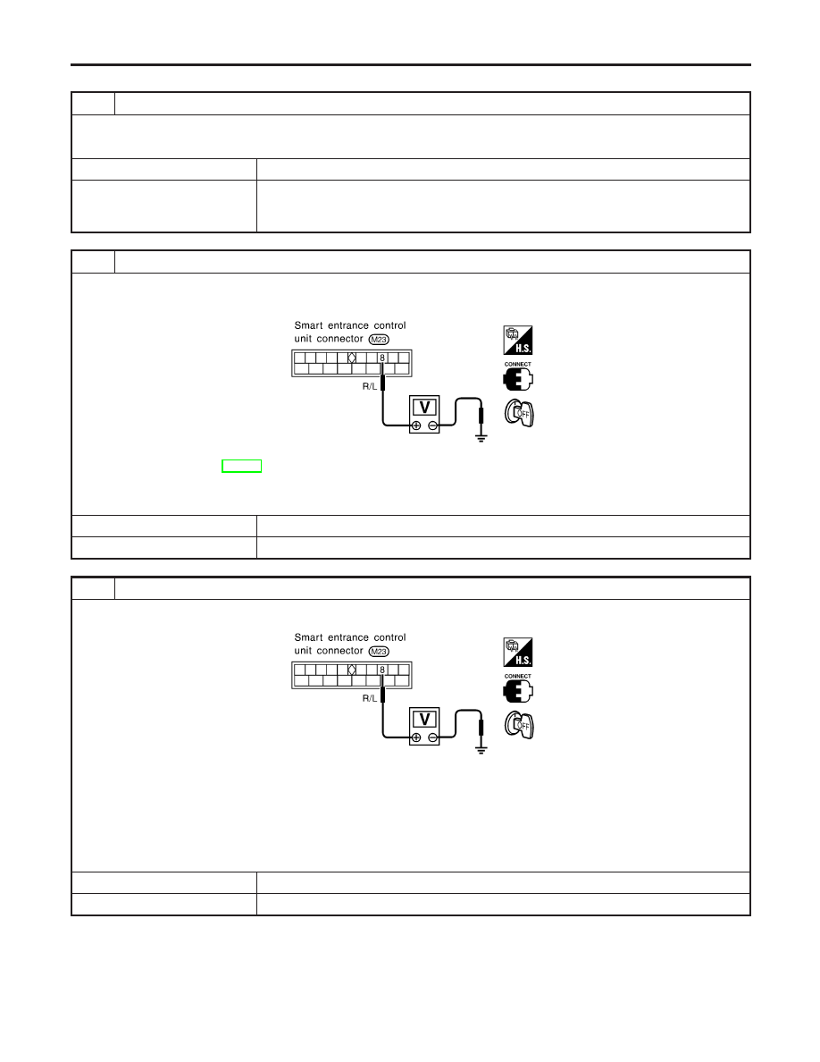
When interior room lamp switch is “DOOR” position, check voltage across smart entrance control unit terminal 8 and
ground.
SEL891VB
Refer to wiring diagram in EL-195.
Battery voltage should exist.
OK or NG
OK
©
GO TO 3.
NG
©
Repair harness between smart entrance control unit and interior room lamp.
3
CHECK CONTROL UNIT OUTPUT
Push unlock button of remote controller and check voltage across control unit terminal 8 and ground.
SEL891VB
Voltage (V):
Unlock button is pushed.
0 (For approx. 30 seconds.)
Unlock button is not pushed.
Battery voltage
OK or NG
OK
©
Check system again.
NG
©
Replace smart entrance control unit.
MULTI-REMOTE CONTROL SYSTEM
Trouble Diagnoses (Cont’d)
EL-208
Нет комментариевНе стесняйтесь поделиться с нами вашим ценным мнением.
Текст