Infiniti G20 (P11). Manual — part 180
MONITOR ITEM
CONDITION
SPECIFICATION
VC/V BYPASS/V
I
Ignition switch: ON
OFF
VENT CONT/V
I
Ignition switch: ON
OFF
COOLING FAN
I
After warming up engine,
idle the engine.
I
Air conditioner switch: OFF
Engine coolant temperature is
94°C (201°F) or less
OFF
Engine coolant temperature is
between 95°C (203°F) and
104°C (219°F)
LOW
Engine coolant temperature is
105°C (221°F) or more
HIGH
HO2S1 HTR (B1)
I
Engine speed: Below 3,200 rpm
ON
I
Engine speed: Above 3,200 rpm
OFF
HO2S2 HTR (B1)
I
Ignition switch: ON (Engine stopped)
I
Engine speed: Above 3,600 rpm
OFF
I
Engine speed: Below 3,600 rpm [After driving for 2 minutes
at a speed of 70 km/h (43 MPH) or more]
ON
Major Sensor Reference Graph in Data Monitor
Mode
NCEC0043
The following are the major sensor reference graphs in “DATA MONITOR” mode.
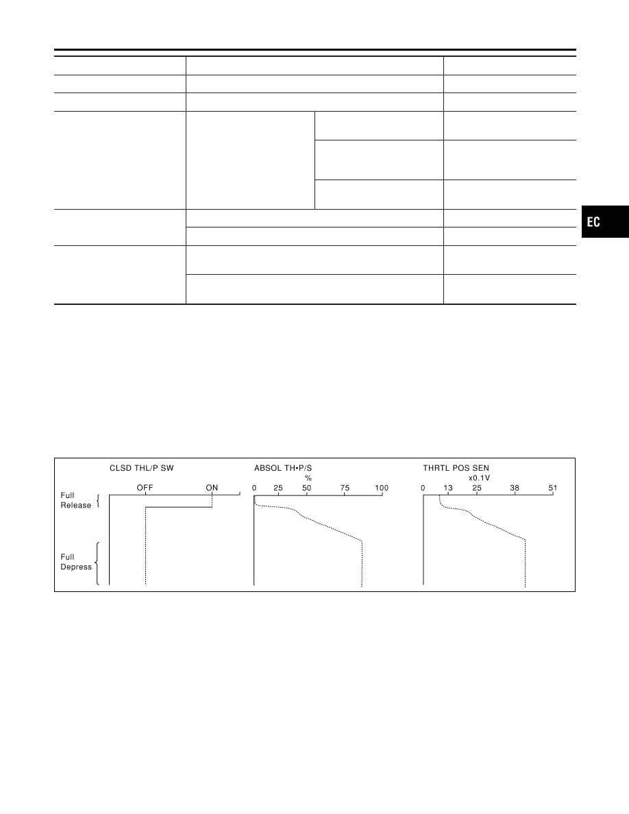
THRTL POS SEN, ABSOL TH·P/S, CLSD THL/P SW
NCEC0043S01
Below is the data for “THRTL POS SEN”, “ABSOL TH·P/S” and “CLSD THL/P SW” when depressing the
accelerator pedal with the ignition switch “ON”.
The signal of “THRTL POS SEN” and “ABSOL TH·P/S” should rise gradually without any intermittent drop or
rise after “CLSD THL/P SW” is changed from “ON” to “OFF”.
SEF240Y
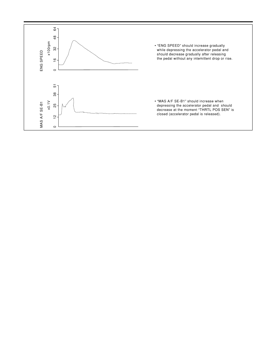
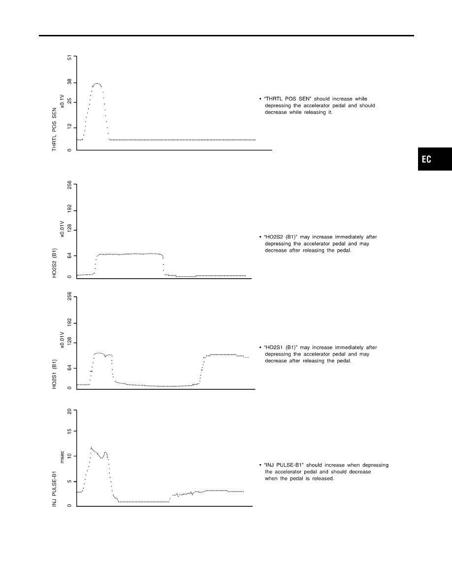
ENG SPEED, MAS A/F SE-B1, THRTL POS SEN, HO2S2 (B1), HO2S1 (B1), INJ PULSE-B1
NCEC0043S02
Below is the data for “ENG SPEED”, “MAS A/F SE-B1”, “THRTL POS SEN”, “HO2S2 (B1)”, “HO2S1 (B1)” and
“INJ PULSE-B1” when revving engine quickly up to 4,800 rpm under no load after warming up engine to nor-
mal operating temperature.
Each value is for reference, the exact value may vary.
GI
MA
EM
LC
FE
CL
MT
AT
AX
SU
BR
ST
RS
BT
HA
SC
EL
IDX
TROUBLE DIAGNOSIS — GENERAL DESCRIPTION
CONSULT-II Reference Value in Data Monitor Mode (Cont’d)
EC-131
SEF241Y
TROUBLE DIAGNOSIS — GENERAL DESCRIPTION
Major Sensor Reference Graph in Data Monitor Mode (Cont’d)
EC-132
SEF242YA
GI
MA
EM
LC
FE
CL
MT
AT
AX
SU
BR
ST
RS
BT
HA
SC
EL
IDX
TROUBLE DIAGNOSIS — GENERAL DESCRIPTION
Major Sensor Reference Graph in Data Monitor Mode (Cont’d)
EC-133
SEF838X
ECM Terminals and Reference Value
NCEC0044
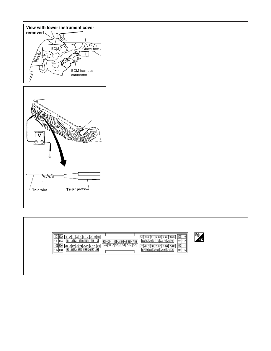
PREPARATION
NCEC0044S01
1.
ECM is located behind the center console. For this inspection:
I
Remove the front passenger center console panel.
2.
Remove ECM harness protector.
SEF367I
3.
Perform all voltage measurements with the connector con-
nected. Extend tester probe as shown to perform tests easily.
I
Open harness securing clip to make testing easier.
I
Use extreme care not to touch 2 pins at one time.
I
Data is for comparison and may not be exact.
CAUTION:
Do not use ECM ground terminals when measuring input/
output voltage. Doing so may result in damage to the ECM’s
transistor. Use a ground other than ECM terminals, such as
the ground.
ECM HARNESS CONNECTOR TERMINAL LAYOUT
NCEC0044S02
SEF970W
ECM INSPECTION TABLE
NCEC0044S03
Specification data are reference values and are measured between
each terminal and ground.
CAUTION:
Do not use ECM ground terminals when measuring input/
output voltage. Doing so may result in damage to the ECM’s
transistor. Use a ground other than ECM terminals, such as
the ground.
TROUBLE DIAGNOSIS — GENERAL DESCRIPTION
ECM Terminals and Reference Value
EC-134
Нет комментариевНе стесняйтесь поделиться с нами вашим ценным мнением.
Текст