Infiniti G20 (P11). Manual — part 181
TERMI-
NAL
NO.
WIRE
COLOR
ITEM
CONDITION
DATA (DC Voltage)
2
PU/R
Vacuum cut valve
bypass valve
[Ignition switch “ON”]
BATTERY VOLTAGE
(11 - 14V)
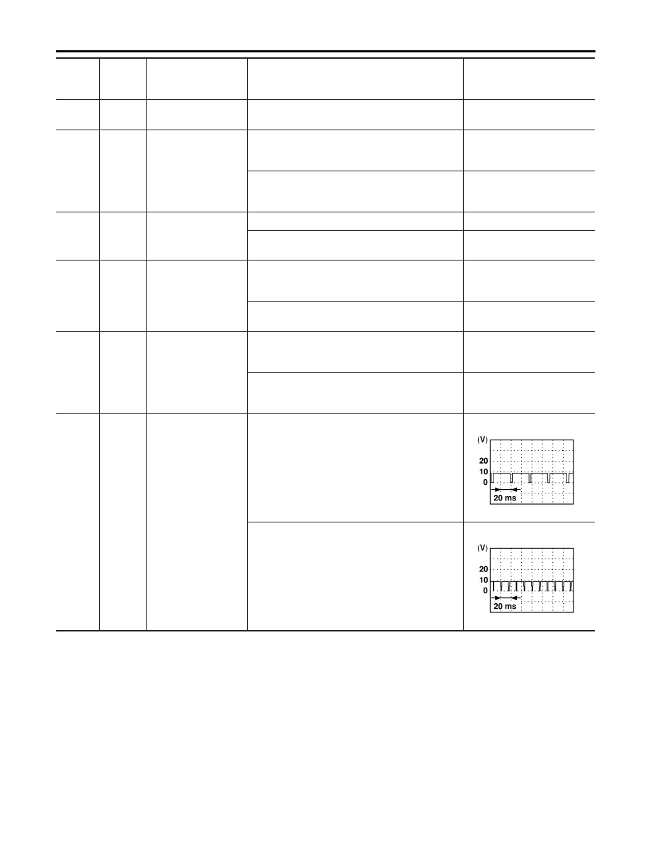
3
R/Y
Heated oxygen sensor
2 heater (rear)
[Engine is running]
I
Engine speed is below 3,600 rpm.
I
After driving for 2 minutes at a speed of 70 km/h
(43 MPH) or more.
0 - 1.0V
[Ignition switch “ON”]
I
Engine stopped
[Engine is running]
I
Engine speed is above 3,600 rpm.
BATTERY VOLTAGE
(11 - 14V)
4
OR
Heated oxygen sensor
1 heater (front)
[Engine is running]
I
Engine speed is below 3,200 rpm.
0 - 1.0V
[Engine is running]
I
Engine speed is above 3,200 rpm.
BATTERY VOLTAGE
(11 - 14V)
6
7
15
16
BR
L
R
G
IACV-AAC valve
[Engine is running]
I
Idle speed
0.1 - 14V
8
9
17
18
SB
W/B
R/W
G/R
EGR volume control
valve
[Engine is running]
I
Idle speed
0.1 - 14V
10
Y/B
A/T signal No. 3
[Engine is running]
I
Idle speed
0 - 1.0V
12
LG
Cooling fan relay
(High)
[Engine is running]
I
Cooling fan is not operating
BATTERY VOLTAGE
(11 - 14V)
[Engine is running]
I
Cooling fan (High) is operating
0 - 0.6V
13
L/Y
Cooling fan relay (Low)
[Engine is running]
I
Cooling fan is not operating
BATTERY VOLTAGE
(11 - 14V)
[Engine is running]
I
Cooling fan is operating
0 - 0.6V
14
P
EVAP canister purge
volume control sole-
noid valve
[Engine is running]
I
Idle speed
BATTERY VOLTAGE
(11 - 14V)
SEF994U
[Engine is running]
I
Engine speed is about 2,000 rpm (More than 100
seconds after starting engine).
BATTERY VOLTAGE
(11 - 14V)
SEF995U
GI
MA
EM
LC
FE
CL
MT
AT
AX
SU
BR
ST
RS
BT
HA
SC
EL
IDX
TROUBLE DIAGNOSIS — GENERAL DESCRIPTION
ECM Terminals and Reference Value (Cont’d)
EC-135
TERMI-
NAL
NO.
WIRE
COLOR
ITEM
CONDITION
DATA (DC Voltage)
19
BR/W
A/T signal No. 5
[Engine is running]
I
Idle speed
Approximately 8V
21
B/P
Fuel pump relay
[Ignition switch “ON”]
I
For 5 seconds after turning ignition switch “ON”
[Engine is running]
0 - 1V
[Ignition switch “ON”]
I
More than 5 seconds after turning ignition switch
“ON”
BATTERY VOLTAGE
(11 - 14V)
22
OR/L
Malfunction indicator
lamp
[Ignition switch “ON”]
0 - 1.0V
[Engine is running]
I
Idle speed
BATTERY VOLTAGE
(11 - 14V)
23
L/W
Air conditioner relay
[Engine is running]
I
Both A/C switch and blower switch are “ON”
(Compressor operates)
0 - 0.6V
[Engine is running]
I
A/C switch is “OFF”
BATTERY VOLTAGE
(11 - 14V)
31
W/G
ECM relay (Self shut-
off)
[Engine is running]
[Ignition switch “OFF”]
I
For 5 seconds after turning ignition switch “OFF”
0 - 1.0V
[Ignition switch “OFF”]
I
5 seconds passed after turning ignition switch
“OFF”
BATTERY VOLTAGE
(11 - 14V)
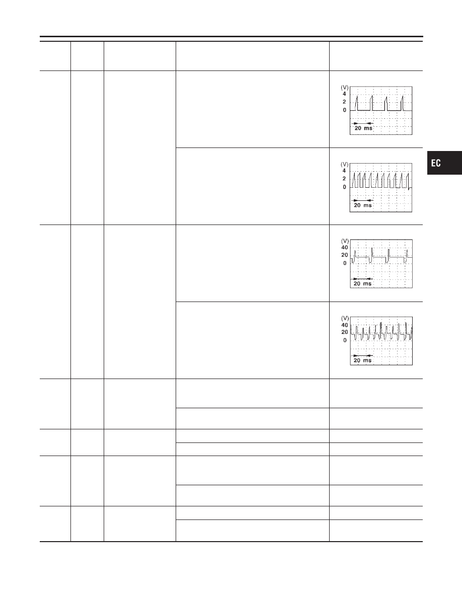
32
L
Tachometer
[Engine is running]
I
Warm-up condition
I
Idle speed
Approximately 8.2V
SEF928X
[Engine is running]
I
Engine speed is 2,000 rpm
Approximately 8.2V
SEF929X
TROUBLE DIAGNOSIS — GENERAL DESCRIPTION
ECM Terminals and Reference Value (Cont’d)
EC-136
TERMI-
NAL
NO.
WIRE
COLOR
ITEM
CONDITION
DATA (DC Voltage)
35
W/B
Ignition signal
[Engine is running]
I
Warm-up condition
I
Idle speed
Approximately 0.3V
SEF996V
[Engine is running]
I
Engine speed is 2,000 rpm
Approximately 0.5V
SEF997V
36
G
Ignition check
[Engine is running]
I
Warm-up condition
I
Idle speed
Approximately 13V
SEF998V
[Engine is running]
I
Engine speed is 2,000 rpm
Approximately 13V
SEF999V
40
Y
Throttle position switch
(Closed position)
[Engine is running]
I
Warm-up condition
I
Accelerator pedal fully released
BATTERY VOLTAGE
(11 - 14V)
[Engine is running]
I
Accelerator pedal depressed
Approximately 0V
41
B/Y
Start signal
[Ignition switch “ON”]
Approximately 0V
[Ignition switch “START”]
9 - 14V
42
G/OR
PNP switch
[Ignition switch “ON”]
I
Gear position is “Neutral position” (M/T models)
I
Gear position is “P” or “N” (A/T models)
Approximately 0V
[Ignition switch “ON”]
I
Except the above gear position
BATTERY VOLTAGE
(11 - 14V)
43
B/R
Ignition switch
[Ignition switch “OFF”]
0V
[Ignition switch “ON”]
BATTERY VOLTAGE
(11 - 14V)
GI
MA
EM
LC
FE
CL
MT
AT
AX
SU
BR
ST
RS
BT
HA
SC
EL
IDX
TROUBLE DIAGNOSIS — GENERAL DESCRIPTION
ECM Terminals and Reference Value (Cont’d)
EC-137
TERMI-
NAL
NO.
WIRE
COLOR
ITEM
CONDITION
DATA (DC Voltage)
44
L/B
Air conditioner switch
[Engine is running]
I
Both A/C switch and blower switch are “ON”
Approximately 0V
[Engine is running]
I
A/C switch is “OFF”
BATTERY VOLTAGE
(11 - 14V)
46
SB
Power steering oil
pressure switch
[Engine is running]
I
Steering wheel is being turned.
Approximately 0V
[Engine is running]
I
Steering wheel is not being turned.
Approximately 5V
48
B
ECM ground
[Engine is running]
I
Idle speed
Engine ground
50
R
Electrical load signal
[Ignition switch “ON”]
I
Lighting switch “2ND” and/or rear window defog-
ger switch “ON”
BATTERY VOLTAGE
(11 - 14V)
[Ignition switch “ON”]
I
Lighting switch and rear window defogger switch
“OFF”
0V
54
Y/R
A/T signal No. 1
[Engine is running]
I
Idle speed
Approximately 0 - 1.0V
55
Y/G
A/T signal No. 2
[Engine is running]
I
Idle speed
Approximately 0 - 1.0V
56
G/Y
A/T signal No. 4
[Engine is running]
I
Idle speed
Approximately 0 - 1.0V
57
B
ECM ground
[Engine is running]
I
Idle speed
Engine ground
58
B
Sensor’s ground
[Engine is running]
I
Warm-up condition
I
Idle speed
Approximately 0V
61
L
Mass air flow sensor
[Engine is running]
I
Warm-up condition
I
Idle speed
1.3 - 1.7V
[Engine is running]
I
Warm-up condition
I
Engine speed is 2,500 rpm
1.8 - 2.4V
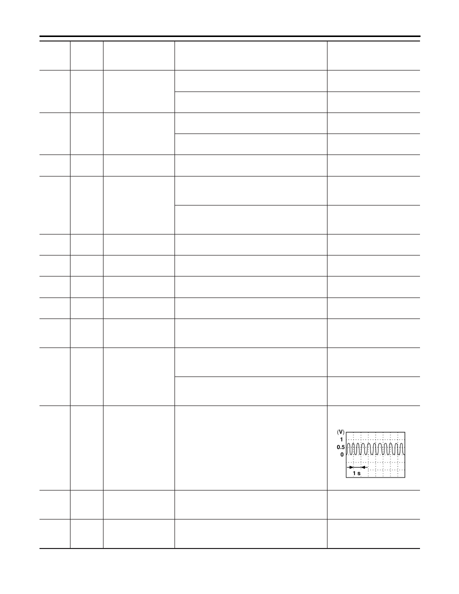
62
W
Heated oxygen sensor
1 (front)
[Engine is running]
I
Warm-up condition
I
Engine speed is 2,000 rpm
0 - Approximately 1.0V
(Periodically change)
SEF059V
63
W
Heated oxygen sensor
2 (rear)
[Engine is running]
I
Warm-up condition
I
Engine speed is 2,000 rpm
0 - Approximately 1.0V
64
R/Y
Intake air temperature
sensor
[Engine is running]
Approximately 0 - 4.8V
Output voltage varies with
intake air temperature.
TROUBLE DIAGNOSIS — GENERAL DESCRIPTION
ECM Terminals and Reference Value (Cont’d)
EC-138
Нет комментариевНе стесняйтесь поделиться с нами вашим ценным мнением.
Текст