Infiniti QX56 (JA60). Manual — part 324
FRONT FINAL DRIVE
DLN-219
< DISASSEMBLY AND ASSEMBLY >
[FRONT FINAL DRIVE: M205]
C
E
F
G
H
I
J
K
L
M
A
B
DLN
N
O
P
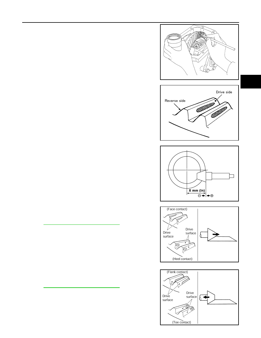
1. Apply red lead to the drive gear.
NOTE:
Apply red lead to both faces of three to four gears, at four loca-
tions evenly spaced on the drive gear.
2. Rotate the drive gear back and forth several times. Then check
for correct drive pinion to drive gear tooth contact as shown.
CAUTION:
Check tooth contact on drive side and reverse side.
3. If the tooth contact is improperly adjusted, follow the procedure
below to adjust the drive pinion height (dimension X).
• If the tooth contact is near the face (face contact), or near the heel
(heel contact), use a thicker drive pinion height adjusting washer to
move drive pinion closer to the drive gear.
DLN-234, "Inspection and Adjustment"
• If the tooth contact is near the flank (flank contact), or near the toe
(toe contact), use a thinner drive pinion height adjusting washer to
move the drive pinion farther from the drive gear.
DLN-234, "Inspection and Adjustment"
SPD357
SDIA0570E
SDIA0517E
PDIA0440E
PDIA0441E

DLN-220
< DISASSEMBLY AND ASSEMBLY >
[FRONT FINAL DRIVE: M205]
FRONT FINAL DRIVE
Backlash
1. Fit a dial indicator to the drive gear face to measure the back-
lash.
• If the backlash is outside of the specification, adjust each side
bearing adjuster.
CAUTION:
Do not change the side bearing adjusters by different
amounts as it will change the side bearing preload torque.
Companion Flange Runout
1. Rotate companion flange and check for runout on the compan-
ion flange face (inner side of the bolt holes) and companion
flange inner side (socket diameter) using suitable tool.
2. If the runout is outside the runout limit, follow the procedure
below to adjust.
a. Rotate the companion flange on the drive pinion by 90
°, 180° and 270° while checking for the position
where the runout is minimum.
b. If the runout is still outside of the runout limit after the companion flange has been rotated on the drive pin-
ion, possible cause could be an assembly malfunction of drive pinion and drive pinion bearing or a mal-
functioning drive pinion bearing.
c.
If the runout is still outside of the runout limit after repair of the assembly of drive pinion and drive pinion
bearing or drive pinion bearing, replace the companion flange.
DISASSEMBLY
Differential Assembly
1. Drain the differential gear oil if necessary.
Backlash
: Refer to
SPD513
If the backlash is greater than specification:
Loosen side bearing adjuster A and tighten side bear-
ing adjuster B by the same amount.
If the backlash is less than specification:
Loosen side bearing adjuster B and tighten side bear-
ing adjuster A by the same amount.
SDIA2262E
Runout limit
Companion flange face
: Refer to
Companion flange inner
side
: Refer to
SDIA2078E

FRONT FINAL DRIVE
DLN-221
< DISASSEMBLY AND ASSEMBLY >
[FRONT FINAL DRIVE: M205]
C
E
F
G
H
I
J
K
L
M
A
B
DLN
N
O
P
2. Remove the differential side shaft and differential side flange
using suitable tool.
3. Remove the extension tube and O-ring from the gear carrier.
4. Place a small hole in the side oil seal case using suitable tool.
5. Remove the side oil seal using Tool as shown.
6. Remove the carrier cover bolts and separate the carrier cover
from the gear carrier using Tool.
CAUTION:
• Do not damage the mating surface.
• Do not insert flat-bladed screwdriver, this will damage the
mating surface.
BDIA0006E
SDIA3205E
LDIA0129E
Tool number
: SP8P
LDIA0130E
Tool number
: KV10111100 (J-37228)
PDIA0699E
DLN-222
< DISASSEMBLY AND ASSEMBLY >
[FRONT FINAL DRIVE: M205]
FRONT FINAL DRIVE
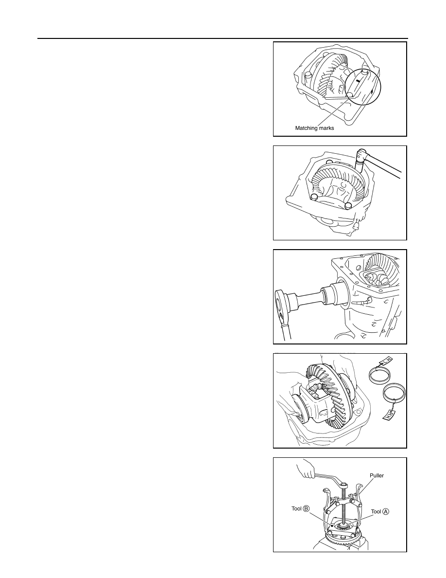
7. For proper reinstallation, paint matching marks on one side of
the side bearing cap and gear carrier.
CAUTION:
• For matching marks, use paint. Do not damage side bear-
ing cap or gear carrier.
• Side bearing caps are line-board during manufacture. The
matching marks are used to reinstall them in their original
positions.
8. Remove the side bearing caps.
9. Remove the side bearing adjuster.
10. Lift the differential case assembly out of the gear carrier.
CAUTION:
Keep side bearing outer races together with side bearing
inner races. Do not mix them up.
11. Remove side bearing inner race using Tools as shown.
CAUTION:
• Do not remove side bearing inner race unless it is being
replaced.
• Place copper plates between the vise and the side bearing
inner race and drive gear to prevent damage.
• Engage puller jaws in groove to prevent damage to bear-
ing.
PDIA0700E
PDIA0701E
SDIA2230E
SPD527
Tool number
A: ST33081000 ( — )
B: ST30021000 ( — )
SDIA2237E
Нет комментариевНе стесняйтесь поделиться с нами вашим ценным мнением.
Текст