Infiniti QX56 (JA60). Manual — part 323
FRONT FINAL DRIVE
DLN-215
< REMOVAL AND INSTALLATION >
[FRONT FINAL DRIVE: M205]
C
E
F
G
H
I
J
K
L
M
A
B
DLN
N
O
P
REMOVAL AND INSTALLATION
FRONT FINAL DRIVE
Removal and Installation
INFOID:0000000005148921
REMOVAL
1. Drain the differential gear oil. Refer to
DLN-209, "Changing Front Differential Gear Oil"
2. Remove the drive shafts from the front final drive assembly. Refer to
FAX-9, "Removal and Installation"
3. Remove the front cross member.
4. Remove the front propeller shaft from the front final drive assembly. Refer to
.
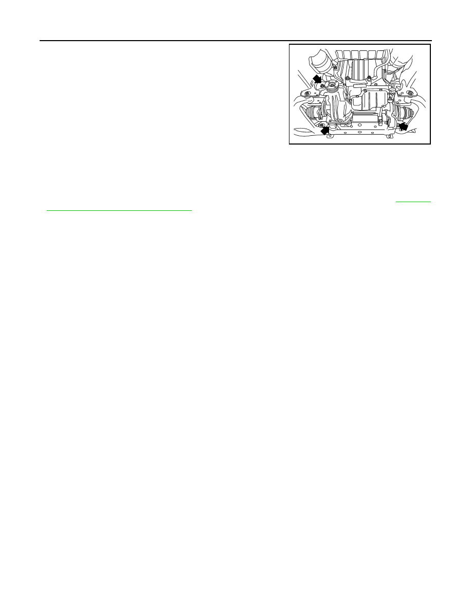
5. Disconnect the vent hose from the front final drive assembly.
6. Support the front final drive assembly using a suitable jack.
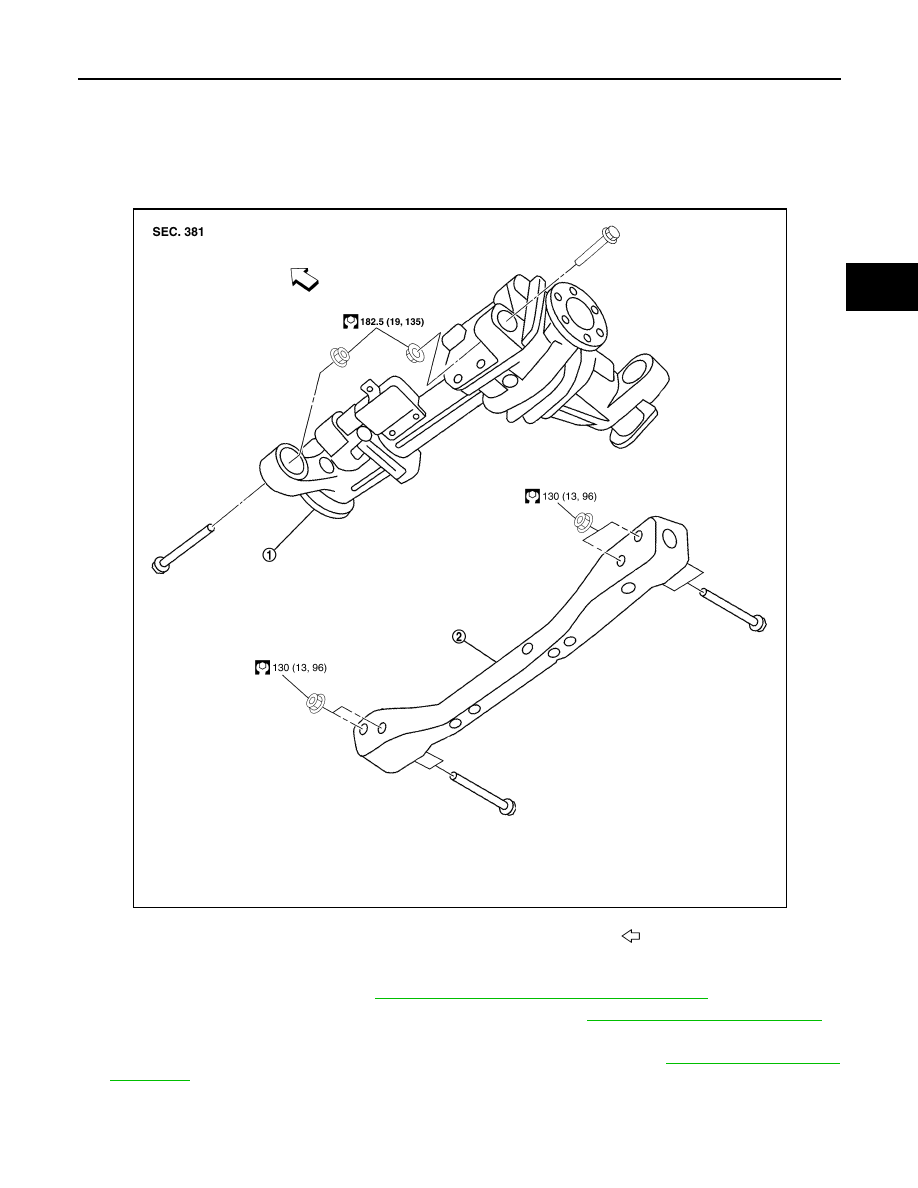
1.
Front final drive assembly
2.
Front cross member
Front
AWDIA0019GB
DLN-216
< REMOVAL AND INSTALLATION >
[FRONT FINAL DRIVE: M205]
FRONT FINAL DRIVE
7. Remove the front final drive assembly bolts, then remove the
front final drive assembly.
CAUTION:
Support the front final drive assembly while removing using
a suitable jack.
INSTALLATION
Installation is in the reverse order of removal.
CAUTION:
• Make sure there are no pinched or restricted areas on the breather hose caused by folding or bend-
ing when installing it.
• Fill the front final drive assembly with differential gear oil after installation. Refer to
"Checking Front Differential Gear Oil"
BDIA0008E
FRONT FINAL DRIVE
DLN-217
< DISASSEMBLY AND ASSEMBLY >
[FRONT FINAL DRIVE: M205]
C
E
F
G
H
I
J
K
L
M
A
B
DLN
N
O
P
DISASSEMBLY AND ASSEMBLY
FRONT FINAL DRIVE
Disassembly and Assembly
INFOID:0000000005148922
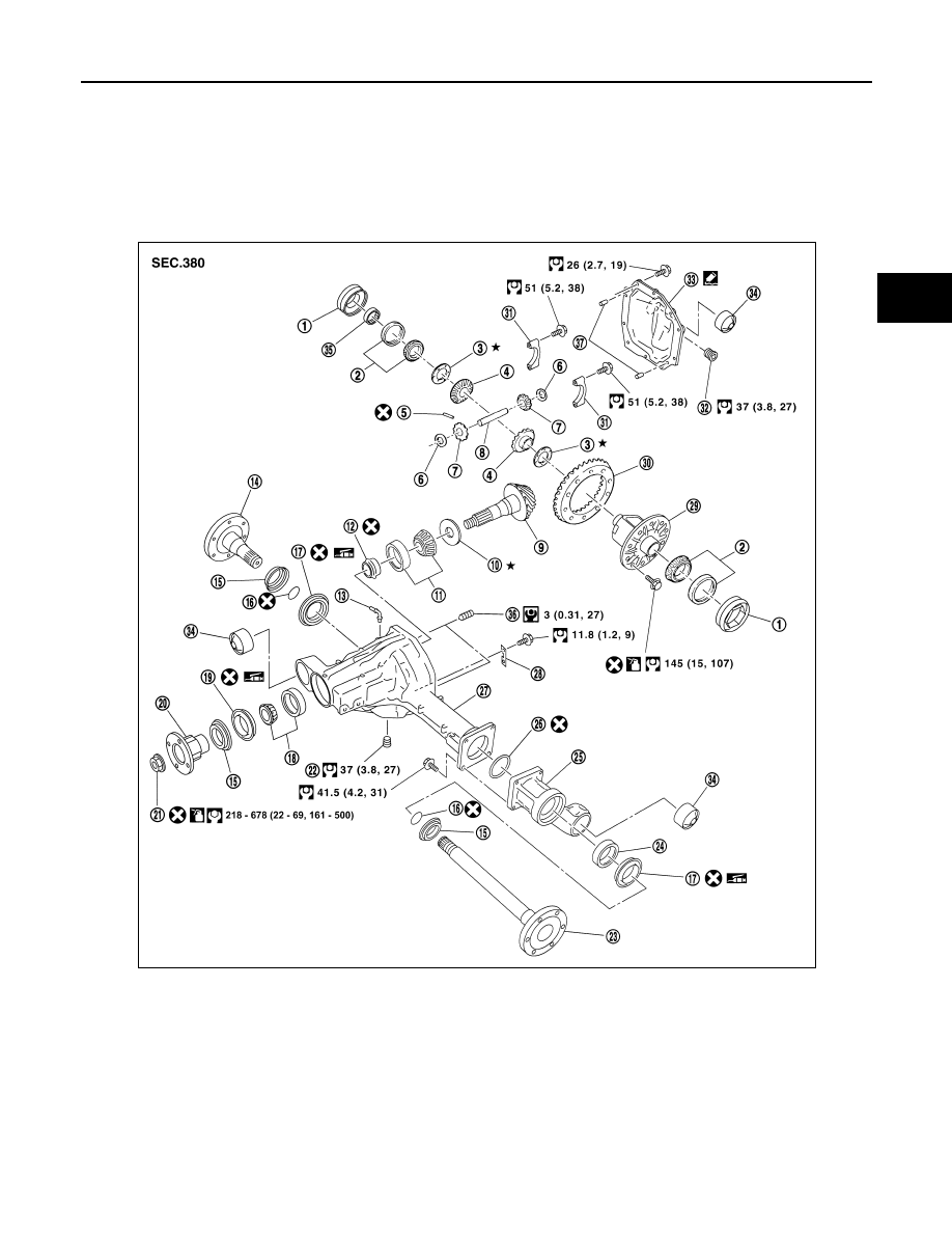
COMPONENTS
1.
Side bearing adjuster
2.
Side bearing
3.
Side gear thrust washer
4.
Side gear
5.
Lock pin
6.
Pinion mate thrust washer
7.
Pinion mate gear
8.
Pinion mate shaft
9.
Drive pinion
10. Drive pinion height adjusting washer 11. Drive pinion rear bearing
12. Collapsible spacer
13. Breather tube
14. Differential side flange
15. Dust shield
16. Circular clip
17. Side oil seal
18. Drive pinion front bearing
19. Front oil seal
20. Companion flange
21. Drive pinion lock nut
22. Drain plug
23. Differential side shaft
24. Differential side shaft bearing
25. Extension tube
26. O-ring
27. Gear carrier
AWDIA0707GB
DLN-218
< DISASSEMBLY AND ASSEMBLY >
[FRONT FINAL DRIVE: M205]
FRONT FINAL DRIVE
ASSEMBLY INSPECTION AND ADJUSTMENT
• Drain the differential gear oil before inspection and adjustment. Refer to
DLN-209, "Changing Front Differen-
.
• Remove and install the carrier cover as necessary for inspection and adjustment. Refer to
Total Preload Torque
1. Install the differential side shaft and differential side flange if necessary.
CAUTION:
The differential side shaft and differential side flange must be installed in order to measure total
preload torque.
2. Rotate the drive pinion back and forth 2 to 3 times to check for unusual noise and rotation malfunction.
3. Rotate the drive pinion at least 20 times to check for smooth operation of the bearings.
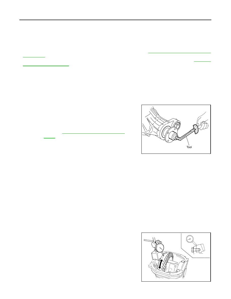
4. Measure total preload torque using Tool.
NOTE:
Total preload torque = Drive pinion bearing preload torque +
Side bearing preload torque
• If the measured value is out of the specification, check and adjust each part. Adjust the drive pinion
bearing preload torque first, then adjust the side bearing preload torque.
Drive Gear Runout
1. Fit a dial indicator to the drive gear back face.
2. Rotate the drive gear to measure runout.
• If the runout is outside of the limit, check the condition of the drive
gear assembly. Foreign material may be caught between the drive
gear and differential case, or the differential case or drive gear may
be deformed.
CAUTION:
Replace drive gear and drive pinion as a set.
Tooth Contact
28. Plate
29. Differential case
30. Drive gear
31. Side bearing cap
32. Filler plug
33. Carrier cover
34. Bushing
35. Bearing
36
Screw
37
Dowel pin
Tool number
: ST3127S000 (J-25765-A)
Total preload torque
: Refer to
DLN-234, "Inspection and Adjust-
PDIA0697E
If the total preload torque is greater than specification
On drive pinion bearings: Replace the collapsible spacer.
On side bearings:
Loosen the side bearing adjuster by the same amount on each
side.
If the total preload torque is less than specification
On drive pinion bearings: Tighten the drive pinion lock nut.
On side bearings:
Tighten the side bearing adjuster by the same amount on each
side.
Runout limit:
0.08 mm (0.0031 in) or less
SPD886
Нет комментариевНе стесняйтесь поделиться с нами вашим ценным мнением.
Текст