Infiniti QX56 (JA60). Manual — part 187

CHG
B TERMINAL CIRCUIT
CHG-11
< COMPONENT DIAGNOSIS >
C
D
E
F
G
H
I
J
K
L
B
A
O
P
N
B TERMINAL CIRCUIT
Description
INFOID:0000000005146559
The terminal “1” circuit supplies power to charge the battery and operate the vehicles electrical system.
Diagnosis Procedure
INFOID:0000000005146560
Regarding Wiring Diagram information, refer to
1.
CHECK TERMINAL “1” CONNECTION
1. Turn ignition switch OFF.
2. Verify terminal “1” is clean and tight.
Is the inspection result normal?
YES
>> GO TO 2.
NO
>> Repair terminal “1” connection. Confirm repair by performing complete Starting/Charging system
test. Refer to diagnostic station instruction manual.
2.
CHECK TERMINAL “1” CIRCUIT
Check voltage between generator connector E204 terminal 1 and
ground.
Is voltage reading as specified?
YES
>> GO TO 3.
NO
>> Check harness for open between generator and fusible
link.
3.
CHECK TERMINAL “1” CONNECTION (VOLTAGE DROP TEST)
1. Start engine, then engine running at idle and warm.
2. Check voltage between battery positive terminal and generator
connector E204 terminal 1.
Is the voltage reading as specified?
YES
>> Terminal “1” circuit is normal. Refer to
NO
>> Check harness between battery and generator for high resistance.
(+)
(-)
Voltage
Connector
Terminal
E204
1
Ground
Battery voltage
ALMIA0197ZZ
(+)
(-)
Voltage
Connector
Terminal
E204
1
Battery positive terminal
Less than 0.2V
ALMIA0198ZZ
CHG-12
< COMPONENT DIAGNOSIS >
L TERMINAL CIRCUIT
L TERMINAL CIRCUIT
Description
INFOID:0000000005146561
The terminal “2” (L) circuit controls the charge warning lamp. The charge warning lamp illuminates when the
ignition switch is set to ON or START. When the generator is providing sufficient voltage with the engine run-
ning, the charge warning lamp will go off. If the charge warning lamp illuminates with the engine running, a
malfunction is indicated.
Diagnosis Procedure
INFOID:0000000005146562
Regarding Wiring Diagram information, refer to
1.
CHECK CHARGE WARNING LAMP CIRCUIT CONNECTION
Verify generator connector E205 terminal 2 is clean and tight.
Is the connection secure?
YES
>> GO TO 2.
NO
>> Repair the connection. Confirm repair by performing complete Starting/Charging system test.
Refer to diagnostic station instruction manual.
2.
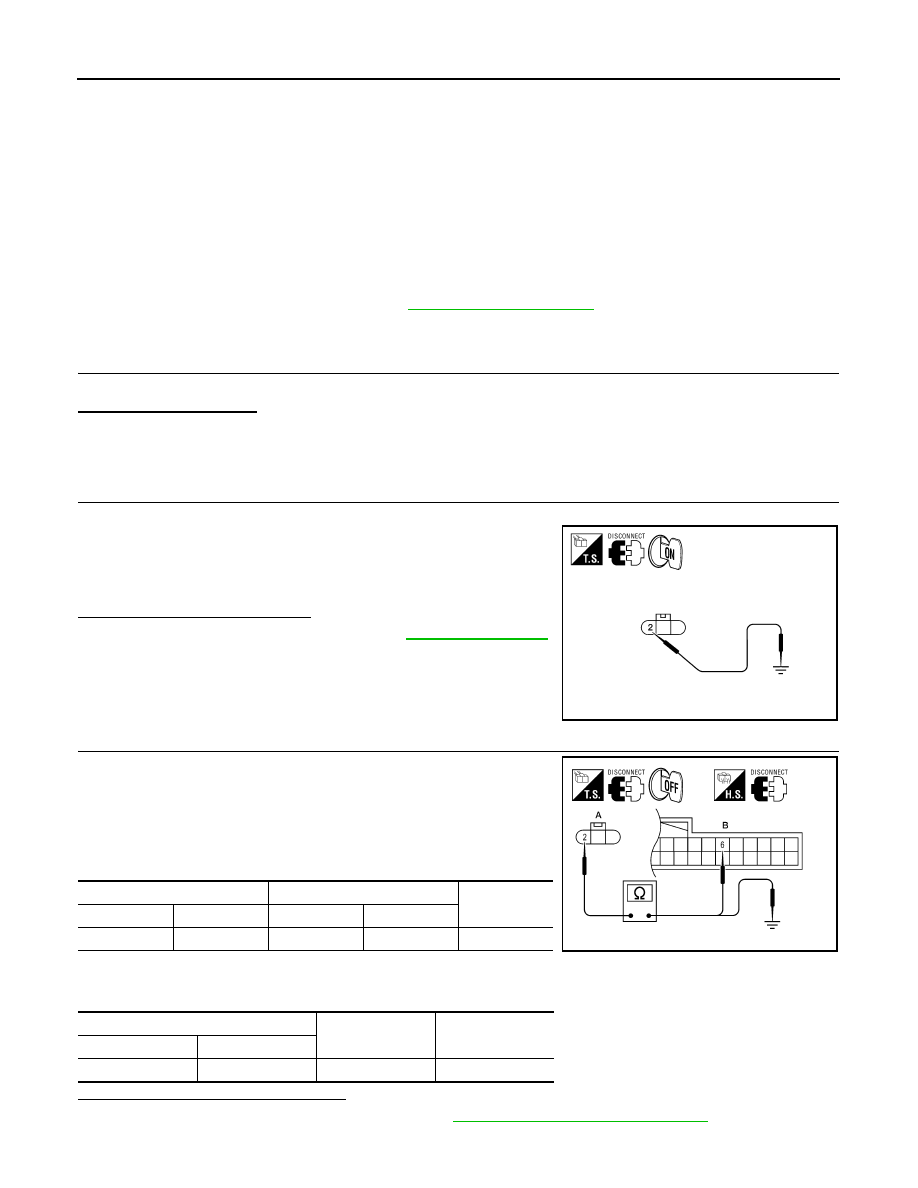
CHECK CHARGE WARNING LAMP CIRCUIT
1. Disconnect generator connector E205.
2. Apply ground to generator harness connector E205 terminal 2
with the ignition switch in the ON position.
Does the charge lamp illuminate?
YES
>> Check generator function. Refer to
.
NO
>> GO TO 3.
3.
CHECK HARNESS CONTINUITY
1. Turn ignition switch OFF.
2. Disconnect the generator connector E205 and combination
meter connector M24.
3. Check continuity between generator harness connector E205
(A) terminal 2 and combination meter harness connector M24
(B) terminal 6.
4. Check continuity between generator harness connector E205
(A) terminal 2 and ground.
Are the continuity results as specified?
YES
>> Replace the combination meter. Refer to
MWI-100, "Removal and Installation"
.
NO
>> Repair the harness or connector.
Charge lamp should illuminate
ALMIA0200ZZ
A
B
Continuity
Connector
Terminal
Connector
Terminal
E205
2
M24
6
Yes
A
—
Continuity
Connector
Terminal
E205
2
Ground
No
AWMIA1099ZZ
CHG
S TERMINAL CIRCUIT
CHG-13
< COMPONENT DIAGNOSIS >
C
D
E
F
G
H
I
J
K
L
B
A
O
P
N
S TERMINAL CIRCUIT
Description
INFOID:0000000005146563
The output voltage of the generator is controlled by the IC regulator at terminal “3” (S) detecting the input volt-
age. Terminal “3” circuit detects the battery voltage to adjust the generator output voltage with the IC regulator.
Diagnosis Procedure
INFOID:0000000005146564
Regarding Wiring Diagram information, refer to
1.
CHECK VOLTAGE REGULATOR CIRCUIT CONNECTION
Check to see if connector E205 terminal 3 is clean and tight.
Is the inspection result normal?
YES
>> GO TO 2.
NO
>> Repair terminal connection. Confirm repair by performing complete Starting/Charging system test.
Refer to diagnostic station instruction manual.
2.
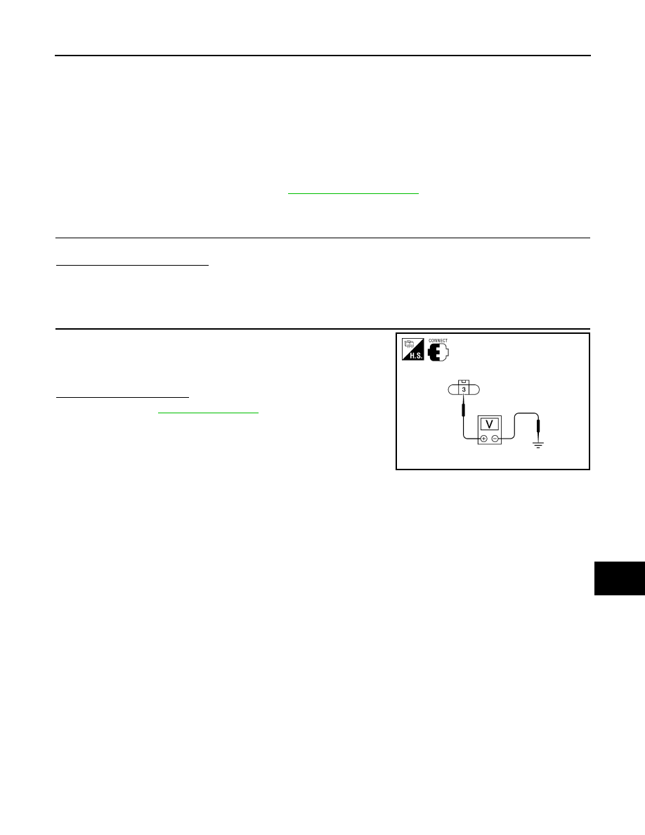
CHECK VOLTAGE REGULATOR CIRCUIT
Check voltage between generator harness connector E205 terminal
3 and ground.
Does battery voltage exist?
YES
>> Refer to
.
NO
>> Check harness for open between generator and fuse.
3 - ground
Battery voltage
ALMIA0201ZZ

CHG-14
< COMPONENT DIAGNOSIS >
CHARGING SYSTEM
CHARGING SYSTEM
Wiring Diagram
INFOID:0000000005146565
ABMWA0376GB
Нет комментариевНе стесняйтесь поделиться с нами вашим ценным мнением.
Текст