Infiniti QX56 (JA60). Manual — part 185
CHG
PRECAUTIONS
CHG-3
< PRECAUTION >
C
D
E
F
G
H
I
J
K
L
B
A
O
P
N
5. When the repair work is completed, return the ignition switch to the
″LOCK″ position before connecting
the battery cables. (At this time, the steering lock mechanism will engage.)
6. Perform a self-diagnosis check of all control units using CONSULT-III.
Precaution for Power Generation Variable Voltage Control System
INFOID:0000000005146547
CAUTION:
For this model, the battery current sensor that is installed to the negative battery cable measures the
charging/discharging current of the battery and performs various engine controls. If an electrical com-
ponent is connected directly to the negative battery terminal, the current flowing through that compo-
nent will not be measured by the battery current sensor. This condition may cause a malfunction of
the engine control system and battery discharge may occur. Do not connect an electrical component
or ground wire directly to the battery terminal.
CHG-4
< PREPARATION >
PREPARATION
PREPARATION
PREPARATION
Special Service Tool
INFOID:0000000005146548
The actual shapes of Kent-Moore tools may differ from those of special service tools illustrated here.
Commercial Service Tool
INFOID:0000000005146549
Tool number
(Kent-Moore No.)
Tool name
Description
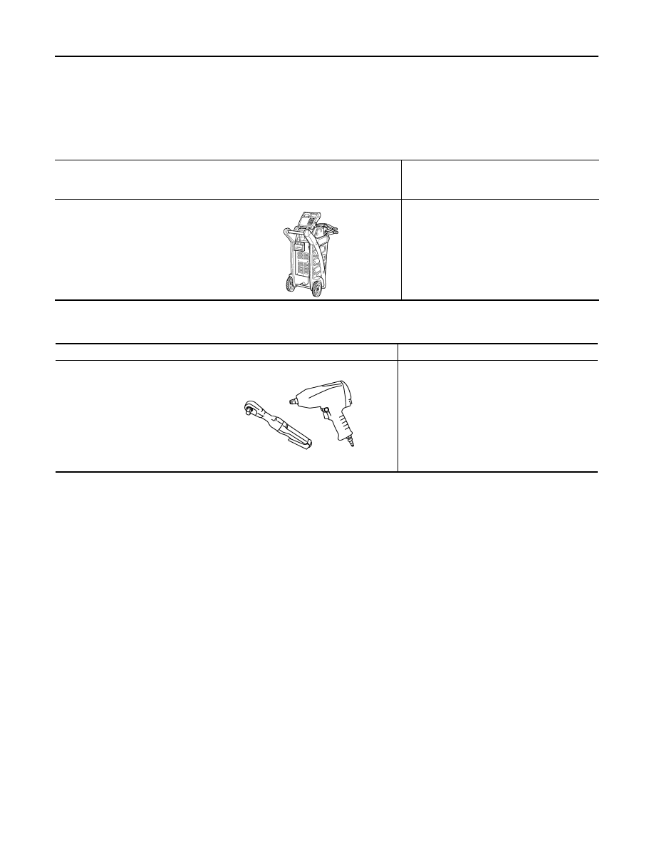
—
(—) Model GR-8
Multitasking Battery Diagnostic Sta-
tion
Tests batteries, starting and charging sys-
tems.
For operating instructions, refer to diagnostic
station instruction manual.
AWIIA1239ZZ
Tool name
Description
Power tool
Loosening bolts and nuts
PBIC0190E
CHG
DIAGNOSIS AND REPAIR WORKFLOW
CHG-5
< BASIC INSPECTION >
C
D
E
F
G
H
I
J
K
L
B
A
O
P
N
BASIC INSPECTION
DIAGNOSIS AND REPAIR WORKFLOW
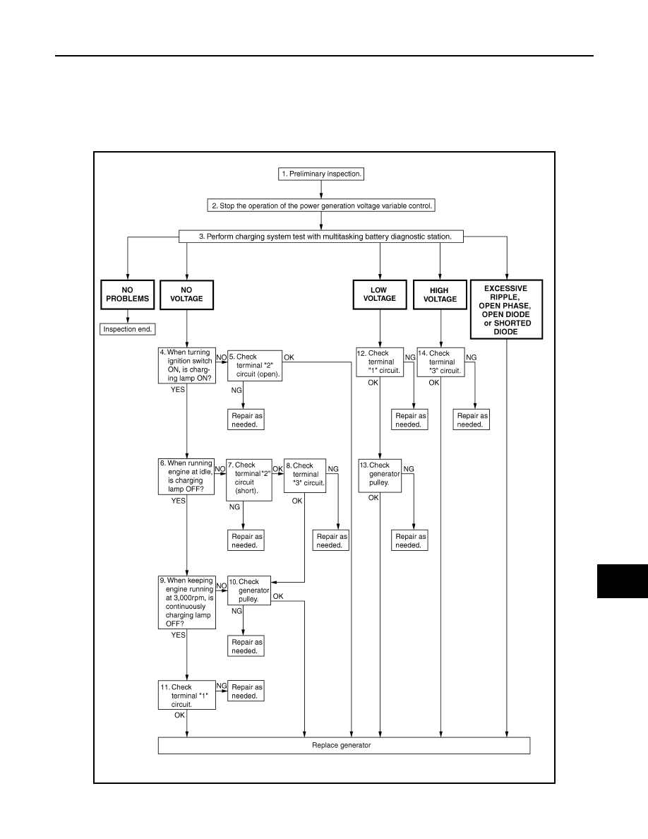
Work Flow
INFOID:0000000005146550
OVERALL SEQUENCE
AWMIA1142GB
CHG-6
< FUNCTION DIAGNOSIS >
CHARGING SYSTEM
FUNCTION DIAGNOSIS
CHARGING SYSTEM
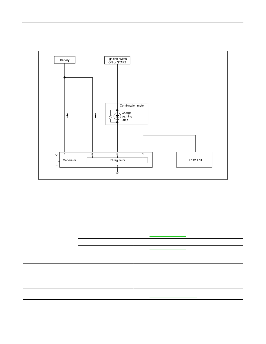
System Diagram
INFOID:0000000005146551
System Description
INFOID:0000000005146552
The generator provides DC voltage to operate the vehicle's electrical system and to keep the battery charged.
The voltage output is controlled by the IC regulator.
Component Description
INFOID:0000000005146553
ALMIA0207GB
Component part
Description
Generator
Terminal “1”
Refer to
Terminal “2”
Refer to
Terminal “3”
Refer to
Terminal “4”
Used for the power generation voltage variable control system.
Refer to
.
Combination meter (Charge warning lamp)
The IC regulator warning function activates to illuminate the
charge warning lamp if any of the following symptoms occur while
generator is operating:
• Excessive voltage is produced.
• No voltage is produced.
IPDM E/R
Used for the power generation voltage variable control system.
Refer to
.
Нет комментариевНе стесняйтесь поделиться с нами вашим ценным мнением.
Текст