Infiniti QX56 (JA60). Manual — part 969
TM-178
< ON-VEHICLE REPAIR >
CONTROL VALVE WITH TCM
i.
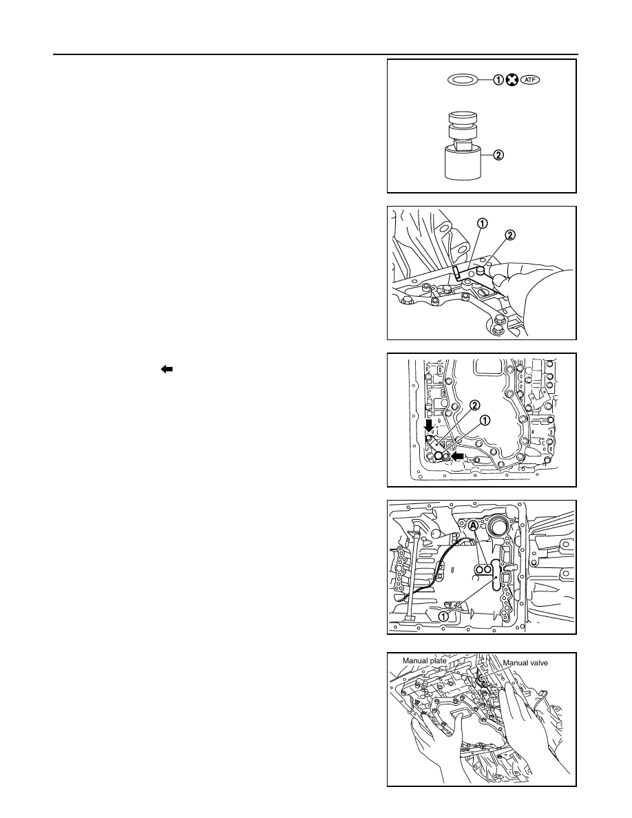
Install new O-ring (1) in plug (2).
CAUTION:
• Do not reuse O-ring.
• Apply ATF to O-ring.
• O-ring should be free of contamination.
ii.
Install plug (2) to bracket (1).
iii. Install plug (1) [with bracket (2)] to control valve with TCM.
Tighten plug bolt (
) to the specified torque.
CAUTION:
Adjust bolt hole of bracket to bolt hole of control valve with
TCM.
6. Install control valve with TCM in transmission case.
CAUTION:
• Make sure that input speed sensor is securely installed
into input speed sensor hole (A).
• Hang down output speed sensor harness toward outside
so as not to disturb installation of control valve with TCM.
• Adjust A/T assembly harness connector of control valve
with TCM to terminal hole of transmission case.
• Assemble it so that manual valve cutout is engaged with
manual plate projection.
JSDIA1313ZZ
JSDIA1312ZZ
JSDIA1311ZZ
1
: Brake band
JSDIA1318ZZ
SCIA5142E
CONTROL VALVE WITH TCM
TM-179
< ON-VEHICLE REPAIR >
C
E
F
G
H
I
J
K
L
M
A
B
TM
N
O
P
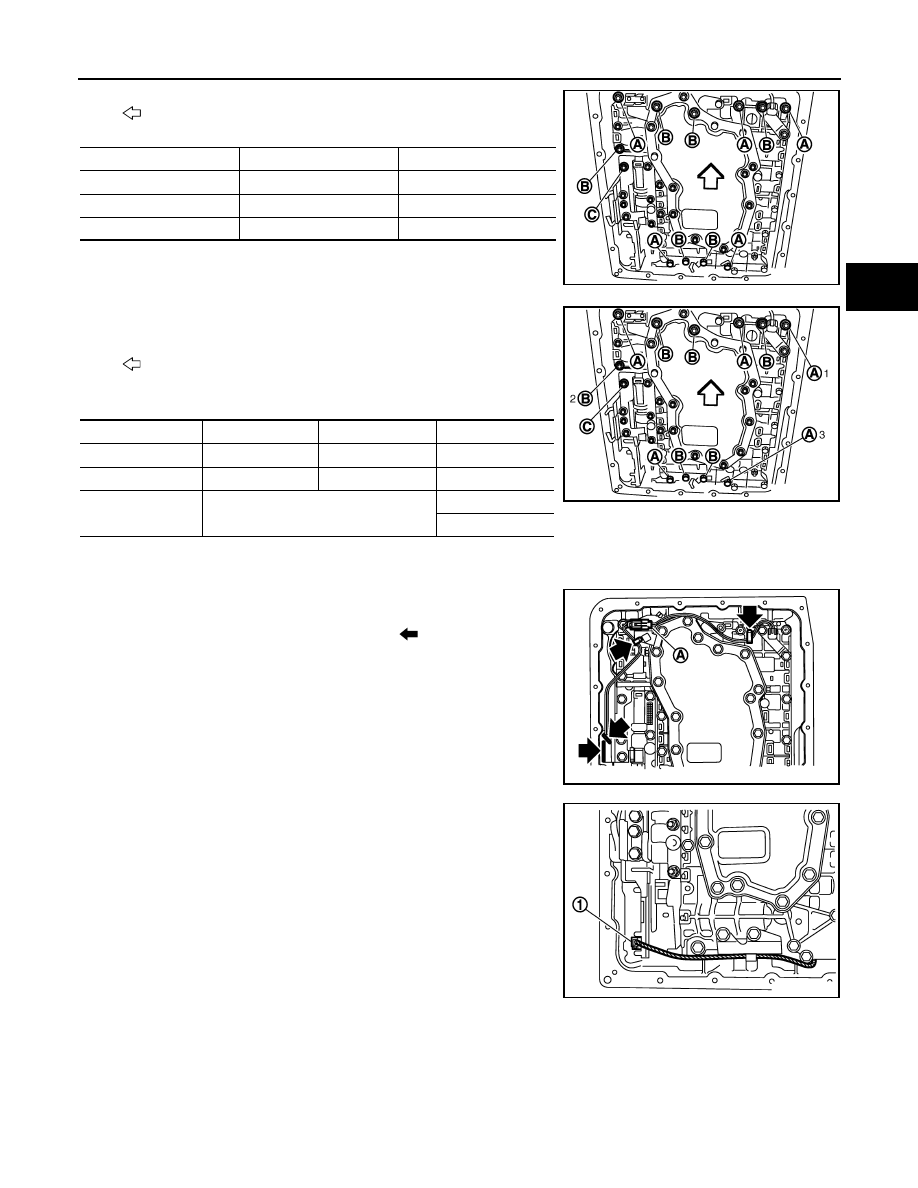
7. Install bolts (A), (B) and (C) in control valve with TCM.
•
: Front
8. Tighten bolt (1), (2) and (3) temporarily to prevent dislocation.
After that tighten them in order (1
→ 2 → 3). Then tighten other
bolts.
•
: Front
9. Tighten control valve with TCM bolts to the specified torque.
10. After installing the A/T fluid temperature sensor 2, connect the A/T fluid temperature sensor 2 connector
as shown below.
a. Connect A/T fluid temperature sensor 2 connector (A).
b. Securely fasten terminal cord assembly and A/T fluid tempera-
ture sensor 2 harness with terminal clips (
).
11. Connect output speed sensor connector (1).
Bolt symbol
Length mm (in)
Number of bolts
A
42 (1.65)
5
B
55 (2.17)
6
C
40 (1.57)
1
SCIA8074E
Bolt symbol
A
B
C
Number of bolts
5
6
1
Length mm (in)
42 (1.65)
55 (2.17)
40 (1.57)
Tightening torque
N·m (km-g, in-lb)
7.9 (0.81, 70)
With ATF applied
7.9 (0.81, 70)
SCIA8075E
SCIA8124E
JSDIA1319ZZ
TM-180
< ON-VEHICLE REPAIR >
CONTROL VALVE WITH TCM
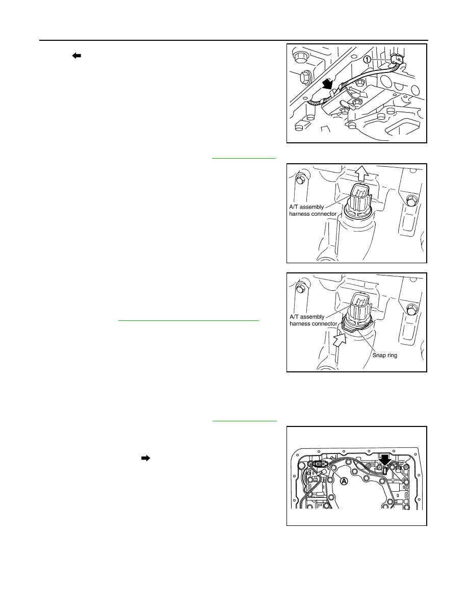
12. Securely fasten output speed sensor (1) harness with terminal
clip (
).
13. Install oil pan to transmission case. Refer to
.
14. Pull up A/T assembly harness connector.
CAUTION:
Do not damage connector.
15. Install snap ring to A/T assembly harness connector.
16. Connect A/T assembly harness connector.
17. Connect the negative battery terminal.
18. Refill the A/T with fluid and check the fluid level and for fluid
leakage. Refer to
TM-148, "Checking the A/T Fluid (ATF)"
.
REMOVAL AND INSTALLATION OF A/T FLUID TEMPERATURE SENSOR 2
Removal
1. Disconnect negative battery terminal.
2. Remove oil pan and oil pan gasket. Refer to
3. Disconnect A/T fluid temperature sensor 2 connector (A).
CAUTION:
Do not damage connector.
4. Straighten terminal clip (
) to free A/T fluid temperature sensor
2 harness.
JSDIA1316ZZ
SCIA5038E
SCIA5039E
SCIA8125E
CONTROL VALVE WITH TCM
TM-181
< ON-VEHICLE REPAIR >
C
E
F
G
H
I
J
K
L
M
A
B
TM
N
O
P
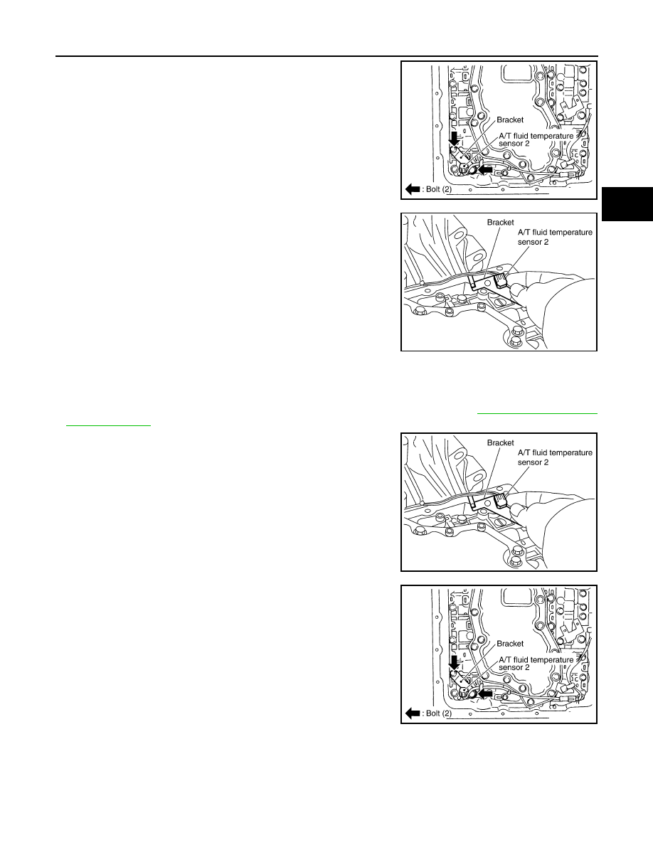
5. Remove A/T fluid temperature sensor 2 with bracket from con-
trol valve with TCM.
6. Remove bracket from A/T fluid temperature sensor 2.
Installation
CAUTION:
• If the A/T fluid temperature sensor 2 has flaws, replace it with a plug.
• After completing installation, check A/T fluid leakage and fluid level. Refer to
1. Install A/T fluid temperature sensor 2 to bracket.
2. Install A/T fluid temperature sensor 2 (with bracket) in control
valve with TCM. Tighten A/T fluid temperature sensor 2 bolt to
the specified torque.
CAUTION:
Adjust bolt hole of bracket to bolt hole of control valve with
TCM.
SCIA5253E
SCIA5264E
SCIA5264E
SCIA5253E
Нет комментариевНе стесняйтесь поделиться с нами вашим ценным мнением.
Текст