Infiniti QX56 (JA60). Manual — part 478
EM-66
< ON-VEHICLE REPAIR >
OIL SEAL
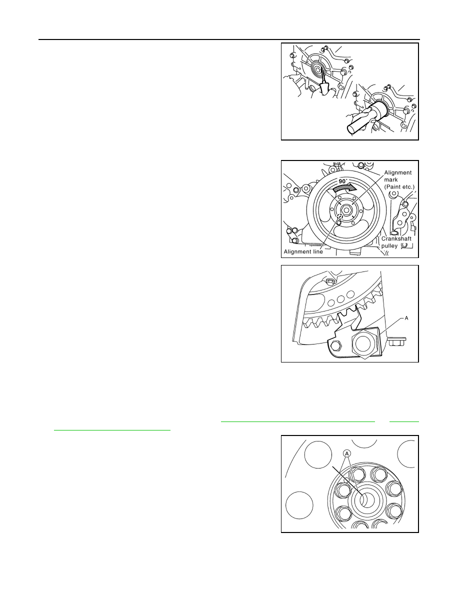
• Press-fit until the height of the front oil seal is level with the
mounting surface using suitable tool.
CAUTION:
• Do not damage front timing chain case and crankshaft.
• Press-fit straight and avoid causing burrs or tilting of the
oil seal.
3. Apply engine oil onto the threaded parts of the crankshaft pulley bolt and seating area.
4. Align the matchmark on the crankshaft pulley bolt flange and the
crankshaft pulley, install crankshaft pulley and tighten bolt to
specifications using Tool.
5. Remove Tool (A).
6. Installation of the remaining components is in the reverse order of removal.
Removal and Installation of Rear Oil Seal
INFOID:0000000005149006
REMOVAL
1. Remove the transmission assembly. Refer to
TM-186, "Removal and Installation (2WD)"
"Removal and Installation (4WD)"
2. Before removing the drive plate, put a match mark (A) on the
crankshaft and drive plate for alignment during installation
3. Remove the drive plate.
PBIC2931E
Crankshaft pulley bolt torque
Step 1
: 93.1 N·m (9.5 kg-m, 69 ft-lb)
Step 2
: additional 90
° (angle tightening)
Tool number
: KV10112100 (BT-8653-A)
KBIA2519E
Tool number
: — (J-47245)
LBIA0455E
ALBIA0522ZZ
OIL SEAL
EM-67
< ON-VEHICLE REPAIR >
C
D
E
F
G
H
I
J
K
L
M
A
EM
N
P
O
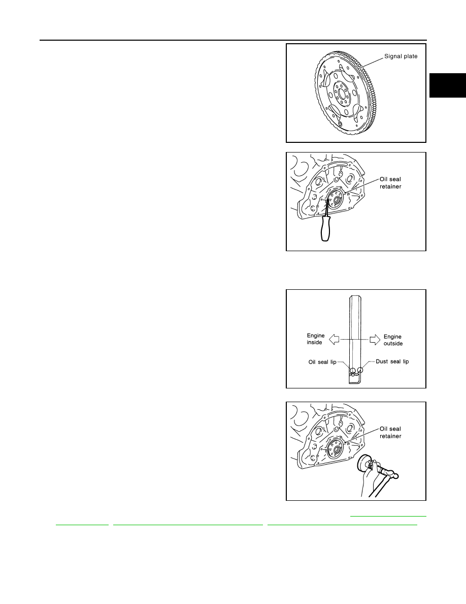
• Holding the crankshaft pulley bolt, lock the crankshaft to
remove the drive plate bolts.
• Remove drive plate bolts diagonally.
CAUTION:
• Do not damage the drive plate. Especially, avoid deform-
ing and damaging the signal plate teeth (circumference
position).
• Keep magnetic materials away from signal plate.
• Place the drive plate with the signal plate surface facing
upward.
4. Remove the rear oil seal using suitable tool.
CAUTION:
Do not damage crankshaft or oil seal retainer surface.
INSTALLATION
1. Apply new engine oil to both the oil seal lip and dust seal lip of the new rear oil seal.
2. Install the rear oil seal.
• Install the rear oil seal so that each seal lip is oriented as
shown.
• Press-fit the rear oil seal using suitable tool.
CAUTION:
• Do not damage the crankshaft or cylinder block.
• Press-fit the oil seal straight to avoid causing burrs or
tilting.
• Do not touch grease applied onto the oil seal lip.
• Do not damage or scratch the outer circumference of
the rear oil seal.
• Tap until flattened with the front edge of the oil seal retainer.
3. Installation of the remaining components is in the reverse order of removal. Refer to
,
TM-186, "Removal and Installation (2WD)"
,
TM-188, "Removal and Installation (4WD)"
.
CAUTION:
• When replacing an engine or transmission you must make sure the dowels are installed cor-
rectly during re-assembly.
• Improper alignment caused by missing dowels may cause vibration, oil leaks or breakage of
drivetrain components.
KBIA2491E
WBIA0437E
SEM715A
WBIA0438E
EM-68
< ON-VEHICLE REPAIR >
CYLINDER HEAD
CYLINDER HEAD
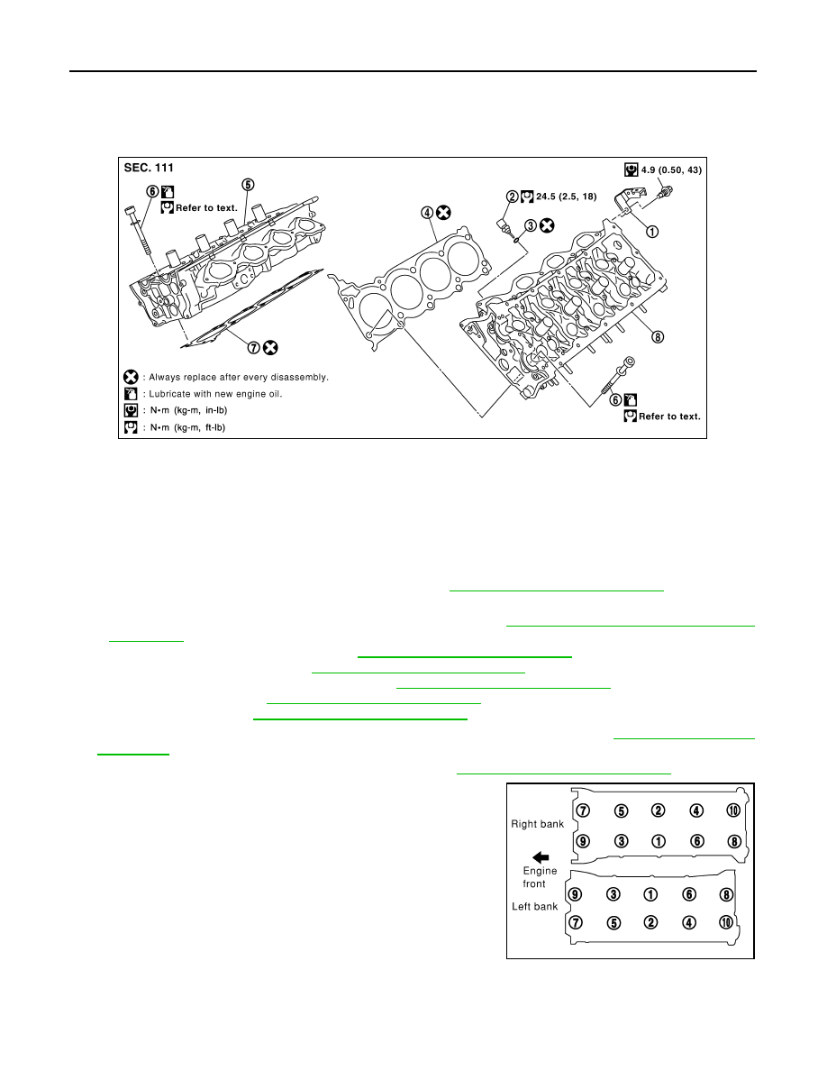
Exploded View
INFOID:0000000005149007
Removal and Installation
INFOID:0000000005149008
REMOVAL
1. Remove the engine assembly from the vehicle. Refer to
EM-78, "Removal and Installation"
2. Remove the following components and related parts:
• Drive belt auto tensioner drive belts and idler pulley. Refer to
EM-14, "Drive Belt Auto Tensioner and
• Thermostat housing and hose. Refer to
CO-22, "Removal and Installation"
.
• Oil pan and oil strainer. Refer to
EM-33, "Removal and Installation"
.
• Fuel tube and fuel injector assembly. Refer to
EM-40, "Removal and Installation"
• Intake manifold. Refer to
EM-26, "Removal and Installation"
• Rocker cover. Refer to
EM-38, "Removal and Installation"
.
3. Remove the crankshaft pulley, front cover, oil pump, and timing chain. Refer to
.
4. Remove the camshaft sprockets and camshafts. Refer to
EM-53, "Removal and Installation"
5. Remove the cylinder head bolts in reverse of order shown.
6. Remove the cylinder heads.
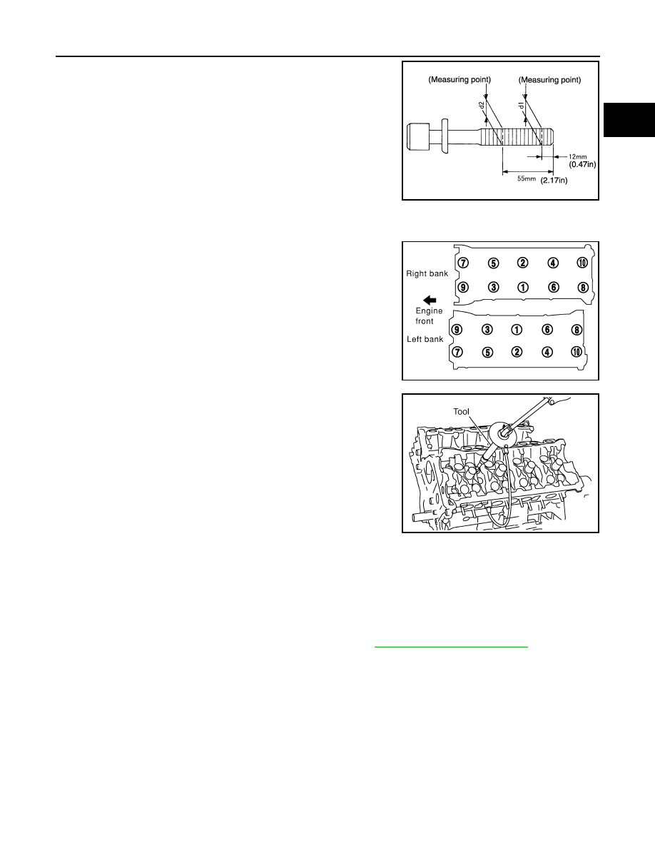
INSPECTION AFTER REMOVAL
Cylinder Head Bolts Diameter
1.
Harness bracket
2.
Engine coolant temperature sensor
3.
Washer
4.
Cylinder head gasket (LH)
5.
Cylinder head (RH)
6.
Cylinder head bolt
7.
Cylinder head gasket (RH)
8.
Cylinder head (LH)
KBIA2528E
PBIC0068E
CYLINDER HEAD
EM-69
< ON-VEHICLE REPAIR >
C
D
E
F
G
H
I
J
K
L
M
A
EM
N
P
O
• Cylinder head bolts are tightened by plastic zone tightening
method. Whenever the size difference between d1 and d2 exceeds
the limit, replace the bolt with a new one.
• If reduction of diameter appears in a position other than d2, use it
as d2 point.
INSTALLATION
1. Install a new cylinder head gasket.
2. Install the cylinder head. Follow the steps below to tighten the
bolts in the numerical order shown.
CAUTION:
• If cylinder head bolts are re-used, check their diameters
before installation. Refer to "Cylinder Head Bolts Diame-
ter".
a. Apply engine oil to threads and seating surface of the bolts.
b. Measure the tightening angle using Tool.
CAUTION:
Measure the tightening angle using Tool. Do not measure
visually.
3. Installation of the remaining components is in the reverse order of removal.
INSPECTION AFTER INSTALLATION
• Before starting the engine, check oil/fluid levels including engine coolant and engine oil. If the levels are
lower than required quantity, fill to the specified level. Refer to
MA-13, "Fluids and Lubricants"
• Use procedure below to check for fuel leakage.
• Turn ignition switch ON (with engine stopped). With fuel pressure applied to the fuel piping, check for fuel
leakage at the connection points.
• Start engine. With engine speed increased, check again for fuel leakage at connection points.
• Run engine to check for unusual noise and vibration.
NOTE:
If hydraulic pressure inside timing chain tensioner drops after removal and installation, slack in the guide
may generate a pounding noise during and just after engine start. However, this is normal. Noise will stop
after hydraulic pressure rises.
• Warm up engine thoroughly to make sure there is no leakage of fuel, exhaust gas, or any oils/fluids including
engine oil and engine coolant.
• Bleed air from passages in lines and hoses, such as in cooling system.
Limit (d1 - d2)
: 0.23 mm (0.0091 in)
KBIA0189E
PBIC0068E
Step a : 44.1 N·m (4.5 kg-m, 33 ft-lb)
Step b : 70
° clockwise
Step c : Loosen in the reverse order of tightening.
Step d : 44.1 N·m (4.5 kg-m, 33 ft-lb)
Step e : 60
° clockwise
Step f
: 60
° clockwise
Tool number
: KV10112100 (BT-8653-A)
WBIA0603E
Нет комментариевНе стесняйтесь поделиться с нами вашим ценным мнением.
Текст