Infiniti QX56 (JA60). Manual — part 476
EM-58
< ON-VEHICLE REPAIR >
CAMSHAFT
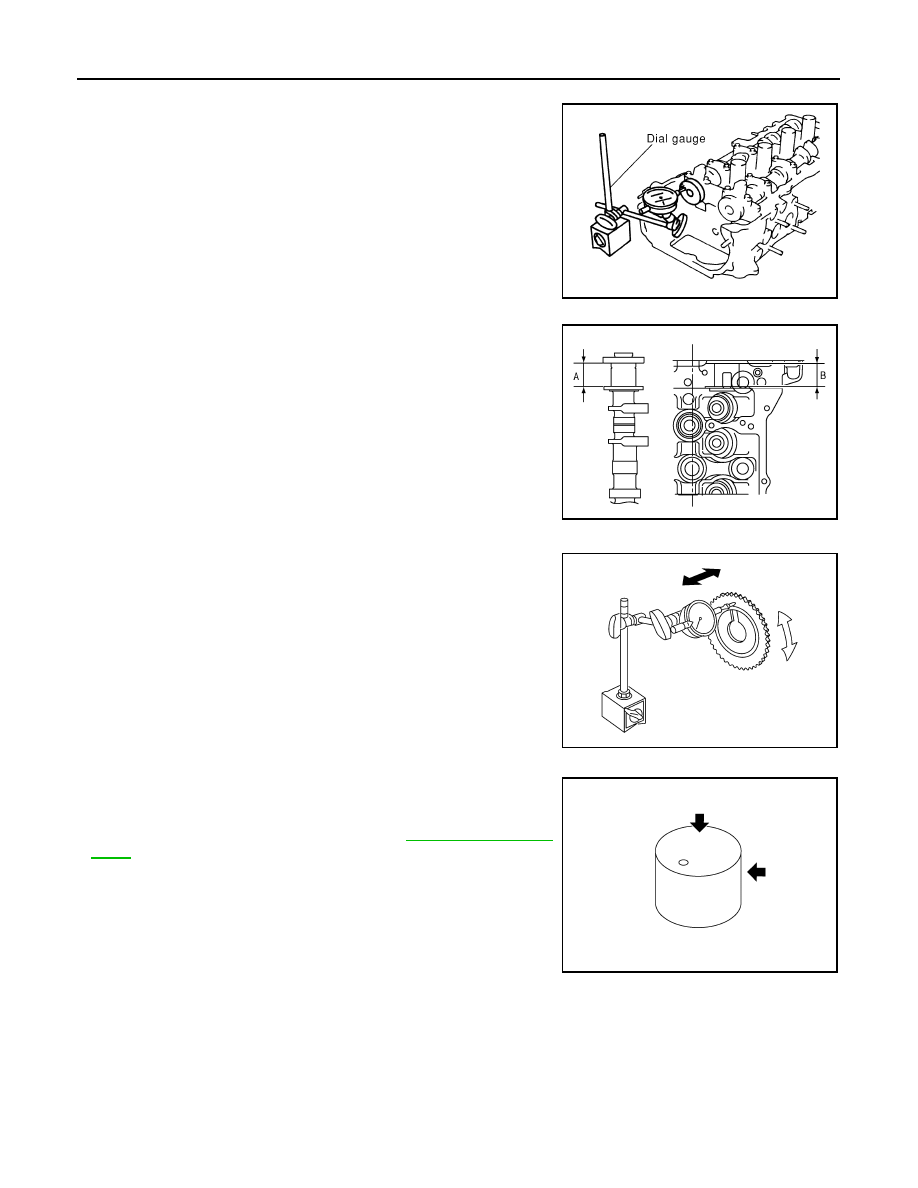
Camshaft End Play
• Install dial gauge in the thrust direction on the front end of the cam-
shaft. Measure the end play when the camshaft is moved forward/
backward (in direction to axis).
• If measurement is out of the specified range, replace the camshaft
and measure again.
• If measurement is still out of the specified range, replace the cylin-
der head.
• Measure the following parts if end play is outside the specified
value.
- Dimension
″A″ for camshaft No. 1 journal
- Dimension
″B″ for cylinder head No. 1 journal
• If measurements are not within specification, replace the camshaft
and/or cylinder head.
Camshaft Sprocket Runout
1. Install the camshaft in the cylinder head.
2. Install the camshaft sprocket to the camshaft.
3. Measure the camshaft sprocket runout.
• If measurement exceeds the specification, replace the cam-
shaft sprocket.
Valve Lifter
Check if the surface of the valve lifter has any wear or cracks.
• If any damage is found, replace the valve lifter.
• Select the thickness of the head so that the valve clearance is
within the standard when replacing. Refer to
Valve Lifter Clearance
Valve Lifter Diameter
Standard
: 0.115 - 0.188 mm (0.0045 - 0.0074 in)
PBIC0042E
Standard
: 30.500 - 30.548 mm (1.2008-1.2027 in)
Standard
: 30.360 - 30.385 mm (1.1953-1.1963 in)
KBIA2426J
Runout
: Less than 0.15 mm (0.0059 in)
KBIA0181J
KBIA0182E
CAMSHAFT
EM-59
< ON-VEHICLE REPAIR >
C
D
E
F
G
H
I
J
K
L
M
A
EM
N
P
O
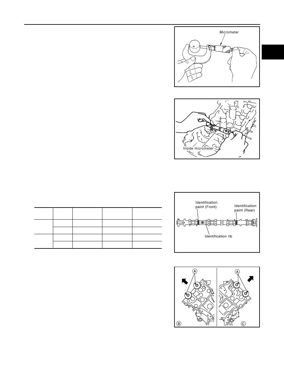
• Measure the diameter of the valve lifter.
Valve Lifter Hole Diameter
• Measure the diameter of the valve lifter hole of the cylinder head,
using suitable tool.
Calculation of Valve Lifter Clearance
(Valve lifter clearance) = (valve lifter hole diameter) – (valve lifter
diameter)
• If the measurement is not within specification, referring to each
specification of the valve lifter diameter and hole diameter, replace
either or both the valve lifter and cylinder head.
INSTALLATION
1. Install the valve lifters if removed.
• Install removed parts in their original locations.
2. Install the camshafts. use the table below for identification of the
RH and LH, and intake and exhaust.
• Install so that the RH bank (B) dowel pins (A) and LH bank (C)
dowel pins (A) at the front of the camshaft face are in the
direction shown.
Standard
: 33.977 - 33.987 mm (1.3377 - 1.3381 in)
JEM798G
Standard
: 34.000 - 34.016 mm (1.3386 - 1.3392 in)
Standard
: 0.013 - 0.039 mm (0.0005 - 0.0015 in)
PBIC0043E
Bank
INT EXH
Identification
paint (front)
Identification
paint (rear)
Identification
rib
RH
INT
Pink
—
Yes
EXH
—
Orange
Yes
LH
INT
Pink
—
No
EXH
—
Orange
No
KBIA2523E
WBIA0708E
EM-60
< ON-VEHICLE REPAIR >
CAMSHAFT
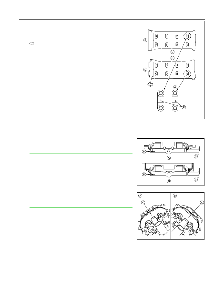
3. Install the RH bank (B) and LH bank (D) camshaft brackets (A).
• Install by referring to the installation location mark (E) on the
upper surface.
• Install so that the installation location mark (E) can be correctly
read when viewed from the intake manifold side (C).
-
: Front
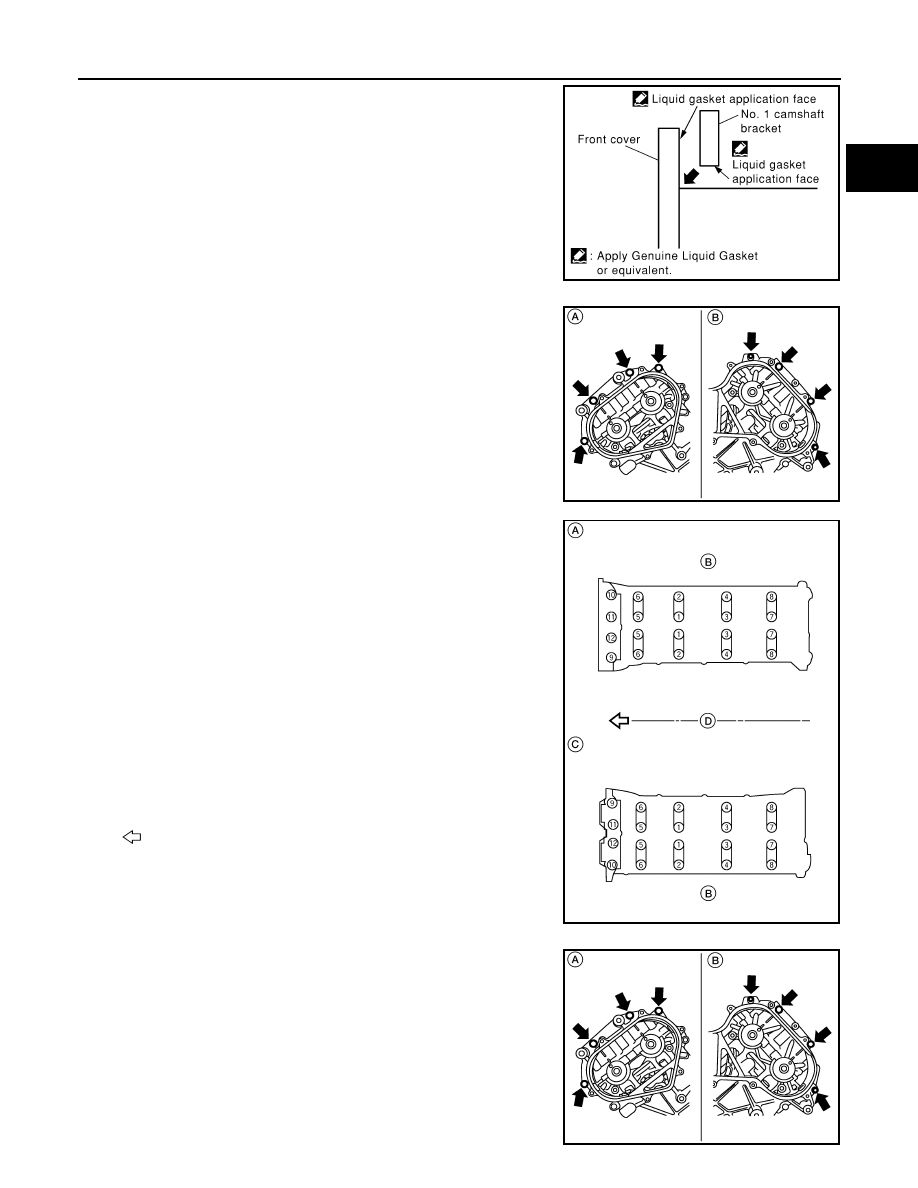
• Install No. 1 camshaft bracket using the following procedure:
• C:11 mm (0.43 in)
• D: 2.0 - 3.0 mm (0.079 - 0.118 in) dia.
- Apply liquid gasket to No. 1 camshaft bracket (A) and (B) as
shown.
Use Genuine RTV Silicone Sealant or equivalent. Refer to
GI-15, "Recommended Chemical Products and Sealants"
.
CAUTION:
• After installation, be sure to wipe off any excessive liq-
uid gasket outside of application (C) and (D) both on RH
and LH sides.
• Remove completely any excess of liquid gasket inside
bracket.
- Apply liquid gasket (C) to the back side of the LH (A) bank
front cover and RH (B) bank front cover as shown.
Use Genuine RTV Silicone Sealant or equivalent. Refer to
GI-15, "Recommended Chemical Products and Sealants"
.
- C: 2.6 - 3.6 mm (0.102 - 0.142 in) dia.
AWBIA0164ZZ
WBIA0710E
WBIA0711E
CAMSHAFT
EM-61
< ON-VEHICLE REPAIR >
C
D
E
F
G
H
I
J
K
L
M
A
EM
N
P
O
- Position No. 1 camshaft bracket close to the mounting posi-
tion, and then install it to prevent from touching liquid gasket
applied to each surface.
- Temporarily tighten the RH (A) and LH (B) front cover bolts (4
for each bank) as shown.
4. Tighten the camshaft bracket bolts as follows:
CAUTION:
After tightening the camshaft bracket bolts, be sure to wipe
off excessive liquid gasket from the parts listed below.
• Mating surface of rocker cover
• Mating surface of front cover
• A: RH bank
• B: Exhaust side
• C: LH bank
• D: Intake side
•
: Front
a. Tighten the RH (A) and LH (B) front cover bolts (4 for each bank)
as shown to the specified torque.
SBIA0259E
WBIA0706E
Camshaft bracket bolts
Step 1 (bolts 9 - 12)
: 1.96 N·m (0.2 kg-m, 17 in-lb)
Step 2 (bolts 1 - 8)
: 1.96 N·m (0.2 kg-m, 17 in-lb)
Step 3 (all bolts)
: 5.88 N·m (0.6 kg-m, 52 in-lb)
Step 4 (all bolts)
: 10.4 N·m (1.1 kg-m, 92 in-lb)
WBIA0707E
Front cover bolts : 11.0 N·m (1.1 kg-m, 8 ft-lb)
WBIA0706E
Нет комментариевНе стесняйтесь поделиться с нами вашим ценным мнением.
Текст