Infiniti QX56 (JA60). Manual — part 225
DOOR SWITCH
DLK-71
< COMPONENT DIAGNOSIS >
[WITH INTELLIGENT KEY SYSTEM]
C
D
E
F
G
H
I
J
L
M
A
B
DLK
N
O
P
DOOR SWITCH
Description
INFOID:0000000005146926
Detects door open/close condition.
Component Function Check
INFOID:0000000005146927
1.
CHECK FUNCTION
With CONSULT-III
Check door switches in data monitor mode with CONSULT-III.
Is the inspection result normal?
YES
>> Door switch is OK.
NO
>> Refer to
.
Diagnosis Procedure
INFOID:0000000005146928
Regarding Wiring Diagram information, refer to
DLK-157, "Wiring Diagram — POWER DOOR LOCK SYS-
1.
CHECK DOOR SWITCHES INPUT SIGNAL
With CONSULT-III
Check door switches ("DOOR SW-DR", "DOOR SW-AS", "DOOR SW-RL", "DOOR SW-RR", "BACK DOOR
SW") in DATA MONITOR mode with CONSULT–III.
• When doors are open:
• When doors are closed:
Without CONSULT-III
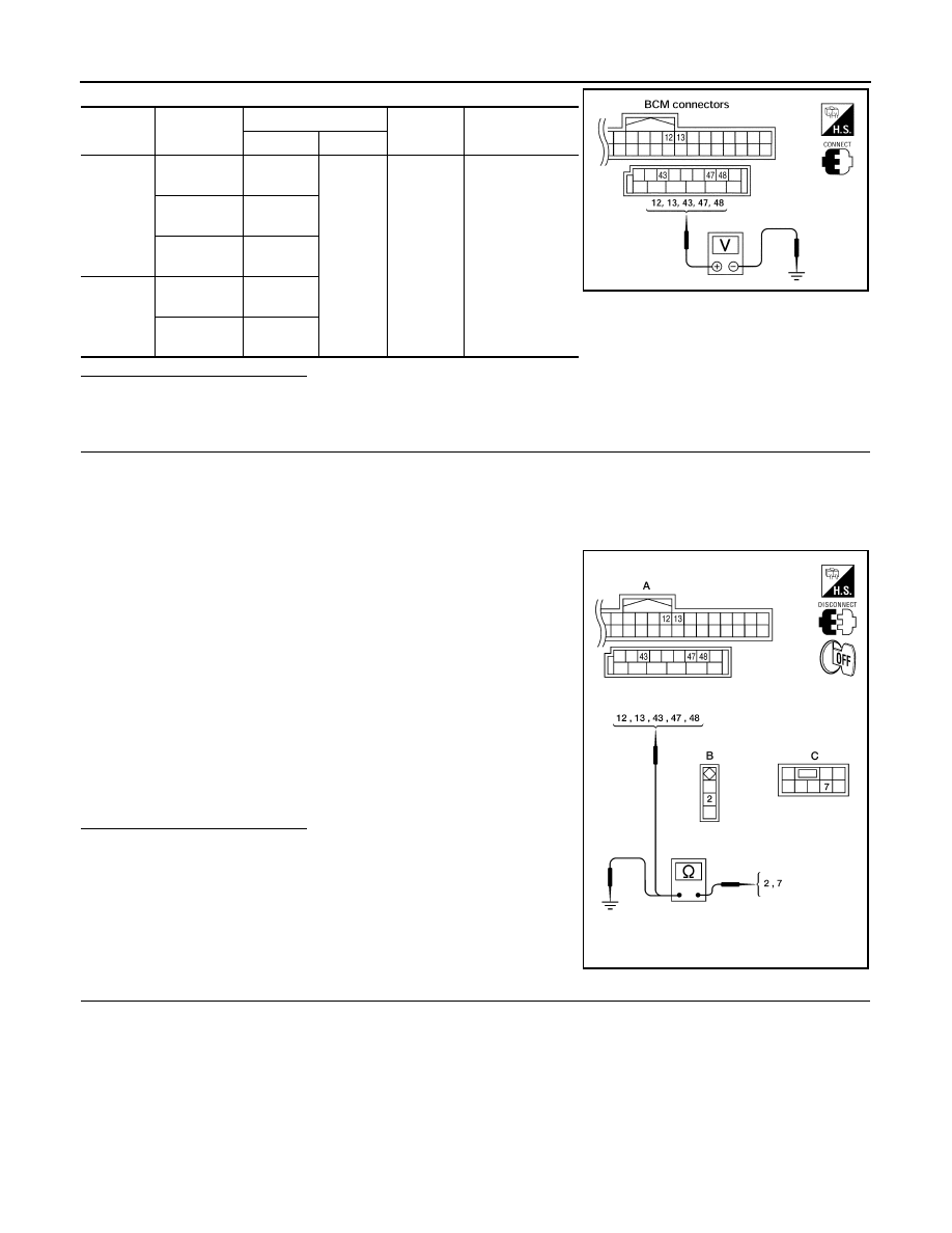
Check voltage between BCM connector M18 or M19 terminals 12, 13, 43, 47, 48 and ground.
Monitor item
Condition
DOOR SW-DR
CLOSE
→ OPEN: OFF → ON
DOOR SW-AS
DOOR SW-RL
DOOR SW-RR
BACK DOOR SW
DOOR SW-DR
:ON
DOOR SW-AS
:ON
DOOR SW-RL
:ON
DOOR SW-RR
:ON
BACK DOOR SW
:ON
DOOR SW-DR
:OFF
DOOR SW-AS
:OFF
DOOR SW-RL
:OFF
DOOR SW-RR
:OFF
BACK DOOR SW
:OFF
DLK-72
< COMPONENT DIAGNOSIS >
[WITH INTELLIGENT KEY SYSTEM]
DOOR SWITCH
Is the inspection result normal?
YES
>> Door switch circuit is OK.
NO
>> GO TO 2
2.
CHECK DOOR SWITCH CIRCUIT
1. Turn ignition switch OFF.
2. Disconnect door switch and BCM.
3. Check continuity between BCM connector (A) M18, M19 terminals 12, 13, 43, 47, 48 and door switch con-
nector (B) B8 (Front LH), B108 (Front RH), B18 (Rear LH), B116 (Rear RH) terminal 2 or back door latch
connector (C) D503 terminal 7.
4. Check continuity between door switch connector (B) B8 (Front
LH), B108 (Front RH), B18 (Rear LH), B116 (Rear RH) terminal
2 or back door latch connector (C) D503 terminal 7 and ground.
Is the inspection result normal?
YES
>> GO TO 3
NO
>> Repair or replace harness.
3.
CHECK DOOR SWITCHES
• Disconnect door switch harness.
• Check continuity between door switch connector terminals.
Connec-
tor
Item
Terminals
Condition
Voltage (V)
(Approx.)
( + )
( – )
M19
Back door
switch/latch
43
Ground
Open
↓
Closed
0
↓
Battery voltage
Front door
switch LH
47
Rear door
switch LH
48
M18
Front door
switch RH
12
Rear door
switch RH
13
LIIA1041E
2 - 47
:Continuity should exist
2 - 12
:Continuity should exist
2 - 48
:Continuity should exist
2 - 13
:Continuity should exist
7 - 43
:Continuity should exist
2 - Ground
:Continuity should not exist
7 - Ground
:Continuity should not exist
ALKIA0689ZZ
DOOR SWITCH
DLK-73
< COMPONENT DIAGNOSIS >
[WITH INTELLIGENT KEY SYSTEM]
C
D
E
F
G
H
I
J
L
M
A
B
DLK
N
O
P
Is the inspection result normal?
YES
>> Door switch circuit is OK.
NO
>> (Front and rear doors) Replace door switch.
NO
>> (Back door) GO TO 4
4.
CHECK BACK DOOR SWITCH CIRCUIT
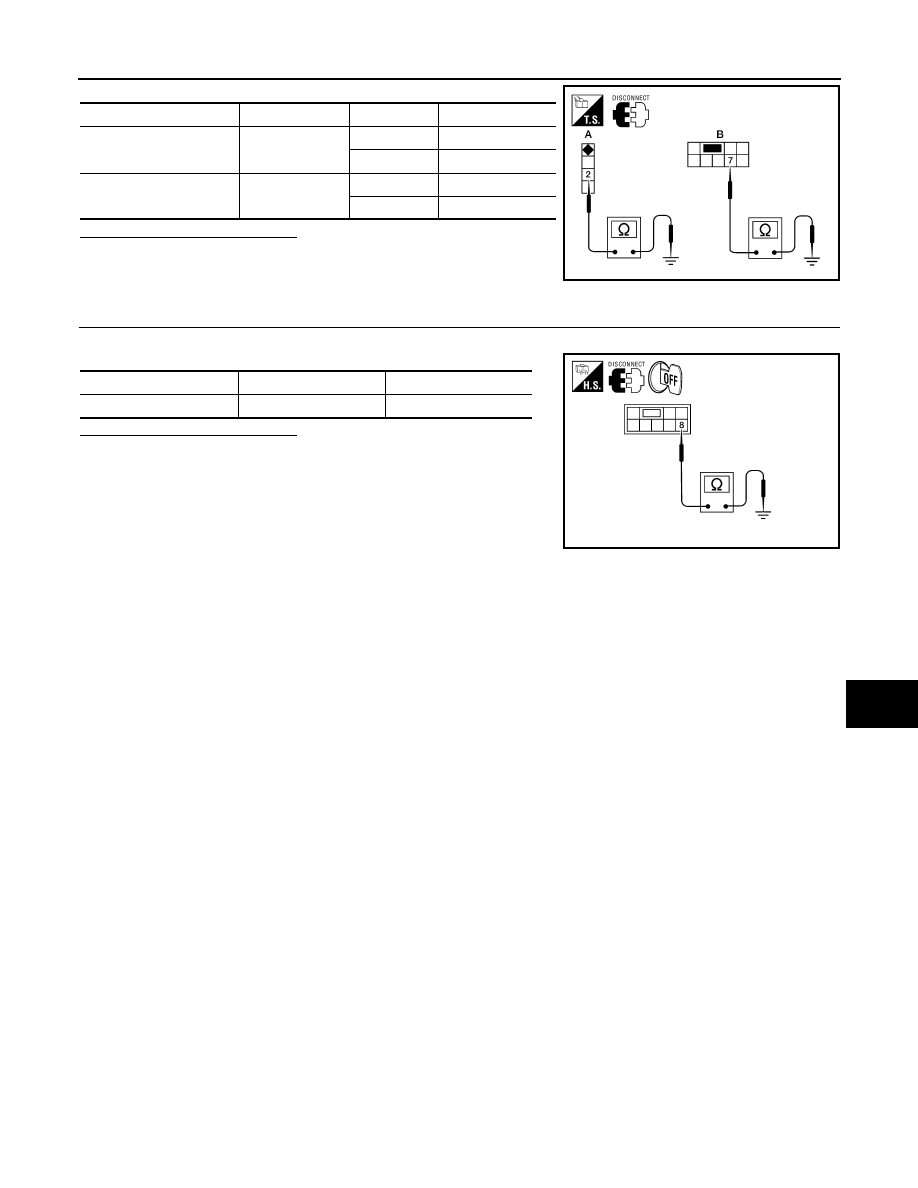
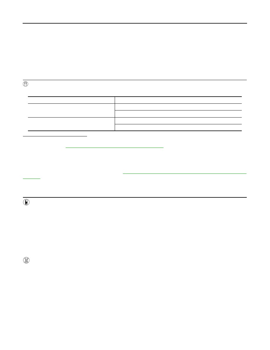
• Check continuity between door switch connector terminal and ground.
Is the inspection result normal?
YES
>> Replace back door switch.
NO
>> Repair or replace harness.
Switch
Terminals
Condition
Continuity
A: Door switch
(front and rear)
2 – Ground
Open
Yes
Closed
No
B: Back door switch
7 – Ground
Open
Yes
Closed
No
ALKIA0690ZZ
Connector
Terminals
Continuity
Back door switch
8 – Ground
Yes
ALKIA0691ZZ
DLK-74
< COMPONENT DIAGNOSIS >
[WITH INTELLIGENT KEY SYSTEM]
DOOR LOCK AND UNLOCK SWITCH
DOOR LOCK AND UNLOCK SWITCH
DRIVER SIDE
DRIVER SIDE : Description
INFOID:0000000005146929
Transmits door lock/unlock operation to BCM.
DRIVER SIDE : Component Function Check
INFOID:0000000005146930
1.
CHECK FUNCTION
With CONSULT-III
Check CDL LOCK SW, CDL UNLOCK SW in Data Monitor mode with CONSULT-III.
Is the inspection result normal?
YES
>> Door lock and unlock switch is OK.
NO
>> Refer to
DLK-74, "DRIVER SIDE : Diagnosis Procedure"
DRIVER SIDE : Diagnosis Procedure
INFOID:0000000005146931
Regarding Wiring Diagram information, refer to
DLK-157, "Wiring Diagram — POWER DOOR LOCK SYS-
1.
CHECK DOOR LOCK/UNLOCK SWITCH INPUT SIGNAL
With CONSULT-III
Check main power window and door lock/unlock switch ("CDL LOCK SW", "CDL UNLOCK SW") in DATA
MONITOR mode in CONSULT–III.
• When main power window and door lock/unlock switch is turned to LOCK:
• When main power window and door lock/unlock switch is turned to UNLOCK:
Without CONSULT-III
1. Remove key from ignition key cylinder.
2. Using an oscilloscope, check the signal between BCM connector M18 terminal 22 and ground when the
main power window and door lock/unlock switch is turned to LOCK or UNLOCK.
3. Make sure the signals which are shown in the figure below can be detected during 10 seconds just after
the door lock/unlock switch is turned to LOCK or UNLOCK.
Monitor item
Condition
CDL LOCK SW
LOCK
: ON
UNLOCK
: OFF
CDL UNLOCK SW
LOCK
: OFF
UNLOCK
: ON
CDL LOCK SW
:ON
CDL UNLOCK SW
:ON
Нет комментариевНе стесняйтесь поделиться с нами вашим ценным мнением.
Текст