Infiniti QX56 (JA60). Manual — part 224
OVERHEAD CONSOLE AREA ANTENNA
DLK-67
< COMPONENT DIAGNOSIS >
[WITH INTELLIGENT KEY SYSTEM]
C
D
E
F
G
H
I
J
L
M
A
B
DLK
N
O
P
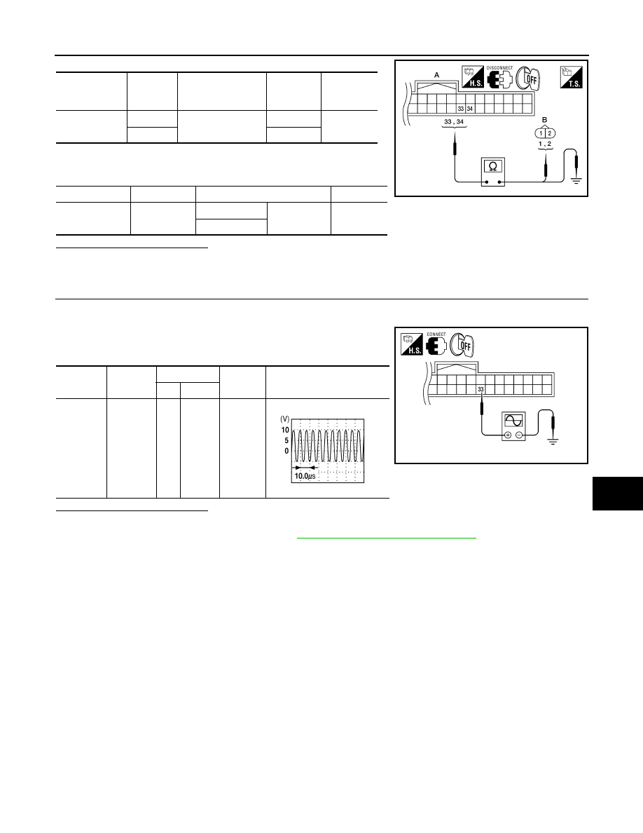
3. Check continuity between Intelligent Key unit harness connector
(A) M70 terminals 33, 34 and ground.
Is the inspection result normal?
YES
>> GO TO 3
NO
>> Repair or replace harness between Intelligent Key unit and overhead console area antenna.
3.
CHECK INSIDE KEY ANTENNA POWER SUPPLY SINGAL
1. Replace overhead console area antenna. (New antenna or other antenna)
2. Connect Intelligent Key unit connector.
3. Check signal between Intelligent Key unit connector and ground
with oscilloscope.
Is the inspection result normal?
YES
>> Replace overhead console area antenna.
NO
>> Replace Intelligent Key unit. Refer to
SEC-120, "Removal and Installation"
Intelligent Key
unit connector
Terminals
Overhead console
area antenna con-
nector
Terminals
Continuity
A: M70
33
B: R210
1
Yes
34
2
Item
Connector
Terminals
Continuity
Intelligent Key
unit
A: M70
33
Ground
No
34
ALKIA0590ZZ
Connector
Item
Terminals
Condition
Signal (V)
(Reference value)
(+)
(–)
M70
Intelligent
Key unit
33
Ground
Ignition
switch is
pushed.
ALKIA0589ZZ
PIIB7441E
DLK-68
< COMPONENT DIAGNOSIS >
[WITH INTELLIGENT KEY SYSTEM]
POWER SUPPLY AND GROUND CIRCUIT
POWER SUPPLY AND GROUND CIRCUIT
INTELLIGENT KEY UNIT
INTELLIGENT KEY UNIT : Diagnosis Procedure
INFOID:0000000005146923
Regarding Wiring Diagram information, refer to
DLK-178, "Wiring Diagram — INTELLIGENT KEY SYSTEM —
1.
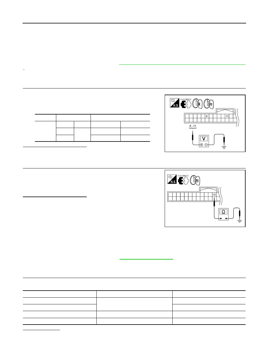
CHECK POWER SUPPLY CIRCUIT
1. Turn ignition switch OFF.
2. Disconnect Intelligent Key unit connector.
3. Check voltage between Intelligent Key unit harness connector
M70 terminals 6, 11 and ground.
Is the inspection result normal?
YES
>> GO TO 2
NO
>> Repair or replace Intelligent Key unit power supply circuit.
2.
CHECK GROUND CIRCUIT
Check continuity between Intelligent Key unit harness connector
M70 terminal 12 and ground.
Is the inspection result normal?
YES
>> Power supply and ground circuits are OK.
NO
>> Repair or replace the Intelligent Key unit ground circuit.
BCM (BODY CONTROL MODULE)
BCM (BODY CONTROL MODULE) : Diagnosis Procedure
INFOID:0000000005380580
Regarding Wiring Diagram information, refer to
.
1.
CHECK FUSES AND FUSIBLE LINK
Check that the following fuses and fusible link are not blown.
Is the fuse blown?
Connector
Terminals
Ignition switch position
M70
(+)
(–)
OFF
ON
6
Ground
0V
Battery voltage
11
Battery voltage
Battery voltage
WIIA1171E
12 - Ground
: Continuity should exist.
WIIA1172E
Terminal No.
Signal name
Fuses and fusible link No.
57
Battery power supply
22 (15A)
70
F (50A)
11
Ignition ACC or ON
4 (10A)
38
Ignition ON or START
59 (10A)
POWER SUPPLY AND GROUND CIRCUIT
DLK-69
< COMPONENT DIAGNOSIS >
[WITH INTELLIGENT KEY SYSTEM]
C
D
E
F
G
H
I
J
L
M
A
B
DLK
N
O
P
YES
>> Replace the blown fuse or fusible link after repairing the affected circuit.
NO
>> GO TO 2
2.
CHECK POWER SUPPLY CIRCUIT
1. Turn ignition switch OFF.
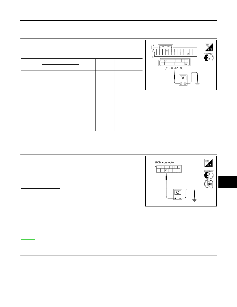
2. Disconnect BCM.
3. Check voltage between BCM harness connector and ground.
Is the measurement value normal?
YES
>> GO TO 3
NO
>> Repair or replace harness.
3.
CHECK GROUND CIRCUIT
Check continuity between BCM harness connector and ground.
Does continuity exist?
YES
>> Inspection End.
NO
>> Repair or replace harness.
BACK DOOR CONTROL UNIT
BACK DOOR CONTROL UNIT : Diagnosis Procedure
INFOID:0000000005146925
Regarding Wiring Diagram information, refer to
DLK-199, "Wiring Diagram—AUTOMATIC BACK DOOR SYS-
1.
BACK DOOR POWER SUPPLY CIRCUIT INSPECTION
1. Turn ignition switch OFF.
2. Disconnect back door control unit connector.
Connector
Terminals
Power
source
Condition
Voltage (V) (Ap-
prox.)
(+)
(-)
M18
11
Ground
ACC
power
supply
Ignition
switch
ACC or
ON
Battery voltage
38
Ground
Ignition
power
supply
Ignition
switch ON
or START
Battery voltage
M20
57
Ground
Battery
power
supply
Ignition
switch
OFF
Battery voltage
70
Ground
Battery
power
supply
Ignition
switch
OFF
Battery voltage
LIIA2415E
BCM
Ground
Continuity
Connector
Terminal
M20
67
Yes
LIIA0915E
DLK-70
< COMPONENT DIAGNOSIS >
[WITH INTELLIGENT KEY SYSTEM]
POWER SUPPLY AND GROUND CIRCUIT
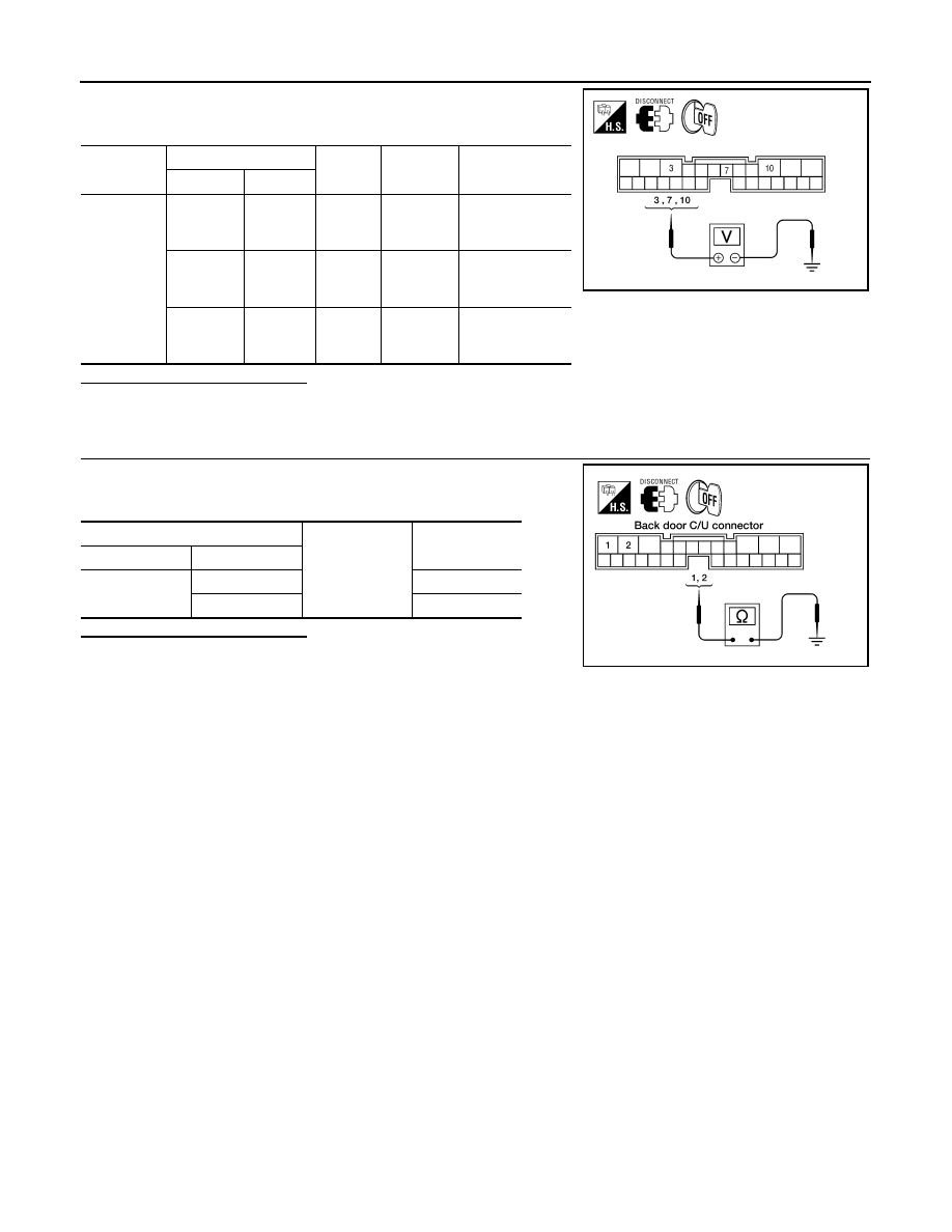
3. Check voltage between back door control unit connector B55
terminals 3, 7, 10 and ground.
Is the inspection result normal?
YES
>> GO TO 2
NO
>> Repair the back door control unit power supply circuit.
2.
BACK DOOR GROUND CIRCUIT INSPECTION
Check continuity between back door control unit connector B55 ter-
minal 1, 2 and ground.
Is the inspection result normal?
YES
>> Circuit is OK.
NO
>> Repair the harness between the back door control unit
and ground.
Connector
Terminals
Power
source
Condition
Voltage (V) (Ap-
prox.)
(+)
(-)
B55
3
Ground
Battery
power
supply
Ignition
switch
OFF
Battery voltage
7
Ground
Ignition
power
supply
Ignition
switch ON
or START
Battery voltage
10
Ground
Battery
power
supply
Ignition
switch
OFF
Battery voltage
ALKIA1604ZZ
BCM
Ground
Continuity
Connector
Terminal
B55
1
Yes
2
Yes
LIIA0801E
Нет комментариевНе стесняйтесь поделиться с нами вашим ценным мнением.
Текст