Infiniti QX56 (JA60). Manual — part 284
P1823 2-4 SOLENOID
DLN-59
< COMPONENT DIAGNOSIS >
[ATX14B]
C
E
F
G
H
I
J
K
L
M
A
B
DLN
N
O
P
Without CONSULT-III
1. Start engine.
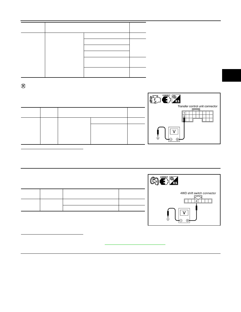
2. Check voltage between transfer control unit harness connector
terminal and ground.
Are the inspection results normal?
YES
>> GO TO 7.
NO
>> GO TO 3.
3.
CHECK 4WD SHIFT SWITCH SIGNAL
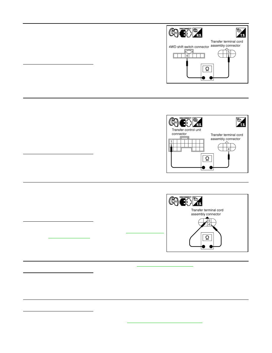
1. Turn ignition switch ON. (Do not start engine.)
2. Check voltage between transfer control unit harness connector
terminals and ground.
Are the inspection results normal?
YES
>> GO TO 4.
NO
>> Check 4WD shift switch. Refer to
DLN-34, "Component Inspection"
4.
CHECK HARNESS BETWEEN 4WD SHIFT SWITCH AND TRANSFER TERMINAL CORD ASSEMBLY
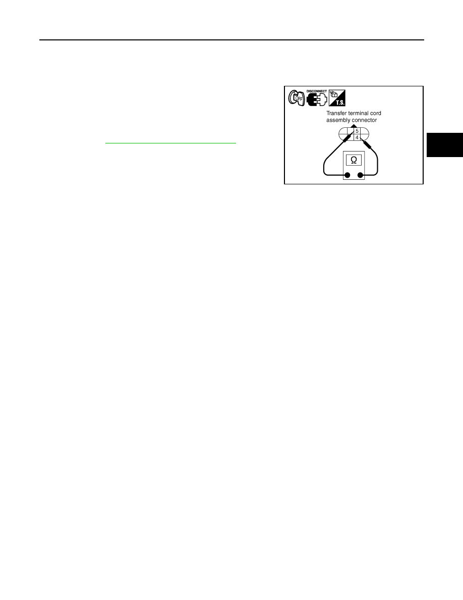
1. Turn ignition switch OFF. (Stay for at least 5 seconds.)
2. Disconnect 4WD shift switch harness connector and transfer terminal cord assembly harness connector.
2-4WD SOL
MON
• Vehicle stopped
• Engine running
• A/T selector lever N
position
• Brake pedal de-
pressed
4WD shift switch: 2WD
OFF
4WD shift switch: AUTO
ON
4WD shift switch: 4H
4WD shift switch: 4LO
4WD shift switch: AUTO
(Wait function is operating.)
OFF
4WD shift switch: 4H (Wait
function is operating.)
OFF
Monitored
item
Condition
Display
value
Connector
Terminal
Condition
Voltage
(Approx.)
E142
1 -
Ground
• Vehicle stopped
• Engine running
• A/T selector lever
N position
• Brake pedal de-
pressed
4WD shift switch: 2WD 0V
4WD shift switch: AU-
TO, 4H or 4LO
Battery
voltage
SDIA2728E
Connector
Terminal
Condition
Voltage (Ap-
prox.)
M141
4 - ground
4WD shift switch: AUTO, 4H or 4LO Battery voltage
4WD shift switch: 2WD
0V
SDIA2729E
DLN-60
< COMPONENT DIAGNOSIS >
[ATX14B]
P1823 2-4 SOLENOID
3. Check continuity between 4WD shift switch harness connector
M141 terminal 4 and transfer terminal cord assembly harness
connector F56 terminal 5.
Also check harness for short to ground and short to power.
Are the inspection results normal?
YES
>> GO TO 5.
NO
>> Repair or replace damaged parts.
5.
CHECK HARNESS BETWEEN TRANSFER CONTROL UNIT AND TRANSFER TERMINAL CORD AS-
SEMBLY
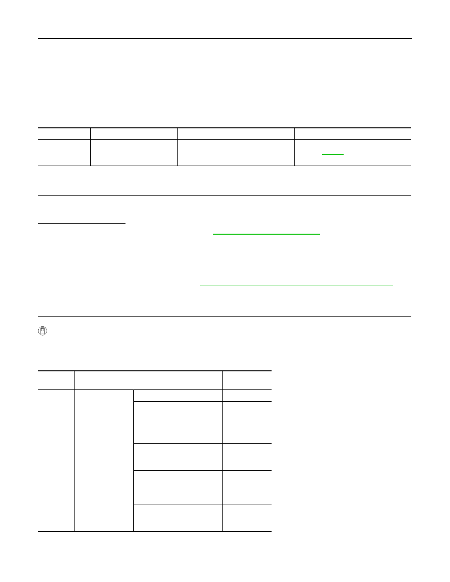
1. Turn ignition switch OFF. (Stay for at least 5 seconds.)
2. Disconnect transfer control unit harness connector and transfer terminal cord assembly harness connec-
tor.
3. Check continuity between transfer control unit harness connec-
tor E142 terminal 1 and transfer terminal cord assembly harness
connector F56 terminal 4.
Also check harness for short to ground and short to power.
Are the inspection results normal?
YES
>> GO TO 6.
NO
>> Repair or replace damaged parts.
6.
CHECK 2-4WD SOLENOID
1. Turn ignition switch OFF. (Stay for at least 5 seconds.)
2. Disconnect transfer terminal cord assembly harness connector.
3. Check resistance between transfer terminal cord assembly ter-
minals 4 and 5.
Are the inspection results normal?
YES
>> GO TO 7.
NO
>> Replace 2-4WD solenoid. Refer to
7.
CHECK TRANSFER CONTROL UNIT
Check transfer control unit input/output signal. Refer to
Are the inspection results normal?
YES
>> GO TO 8.
NO
>> Check transfer control unit pin terminals for damage or loose connection with harness connector.
If any items are damaged, repair or replace damaged parts.
8.
CHECK DTC
Perform the self-diagnosis, after driving a vehicle for a while.
Are the inspection results normal?
YES
>> Inspection End.
NO
>> Replace transfer control unit. Refer to
DLN-130, "Removal and Installation"
.
Continuity should exist.
SDIA2731E
Continuity should exist.
SDIA2732E
4 - 5
: Approx. 22.8 - 25.2
Ω
WDIA0187E
P1823 2-4 SOLENOID
DLN-61
< COMPONENT DIAGNOSIS >
[ATX14B]
C
E
F
G
H
I
J
K
L
M
A
B
DLN
N
O
P
Component Inspection
INFOID:0000000005148824
1. Turn ignition switch OFF. (Stay for at least 5 seconds.)
2. Disconnect transfer terminal cord assembly harness connector.
3. Check resistance between transfer terminal cord assembly ter-
minals 4 and 5.
4. If the inspection results are abnormal replace the 2-4WD sole-
noid. Refer to
DLN-16, "Component Parts Location"
.
4 - 5
: Approx. 22.8 - 25.2
Ω
WDIA0187E
DLN-62
< COMPONENT DIAGNOSIS >
[ATX14B]
P1824 TRANSFER MOTOR
P1824 TRANSFER MOTOR
Description
INFOID:0000000005148825
Motor does not operate properly due to open or short circuit in transfer motor or transfer motor relay.
DTC Logic
INFOID:0000000005148826
DTC DETECTION LOGIC
DTC CONFIRMATION PROCEDURE
1.
DTC CONFIRMATION PROCEDURE
1. Turn ignition switch ON.
2. Perform self-diagnosis.
Is DTC P1824 displayed?
YES
>> Perform diagnosis procedure. Refer to
.
NO
>> Inspection End.
Diagnosis Procedure
INFOID:0000000005148827
Regarding Wiring Diagram information, refer to
DLN-89, "Wiring Diagram - ALL-MODE 4WD SYSTEM -"
.
1.
CHECK TRANSFER MOTOR RELAY SIGNAL
With CONSULT-III
1. Start engine.
2. Select DATA MONITOR mode for ALL MODE AWD/4WD with CONSULT-III.
3. Read out the value of MOTOR RELAY and MOTOR RELAY MON.
DTC
CONSULT-III
Diagnostic item is detected when...
Reference
[P1824]
MOTOR RELAY
Motor does not operate properly due to
open or short circuit in transfer motor or
transfer motor relay.
Refer to
.
Monitored
item
Condition
Display value
(Approx.)
MOTOR
RELAY
• Accelerator ped-
al depressed
• Vehicle stopped
• Engine running
• Brake pedal de-
pressed
4WD shift switch: 2WD
OFF
4WD shift switch: AUTO or
4LO (A/T selector lever P or N
position)
OFF
(ON for approx.
2 sec. after
shifting to P and
N.)
4WD shift switch: AUTO or
4LO (Except for A/T selector
lever P or N position)
ON
4WD shift switch: 4H (A/T se-
lector lever P position)
OFF
(ON for approx.
2 sec. after
shifting to P.)
4WD shift switch: 4H (Except
for A/T selector lever P posi-
tion)
ON
Нет комментариевНе стесняйтесь поделиться с нами вашим ценным мнением.
Текст