Infiniti QX56 (JA60). Manual — part 282
P1819 TRANSFER CONTROL DEVICE
DLN-51
< COMPONENT DIAGNOSIS >
[ATX14B]
C
E
F
G
H
I
J
K
L
M
A
B
DLN
N
O
P
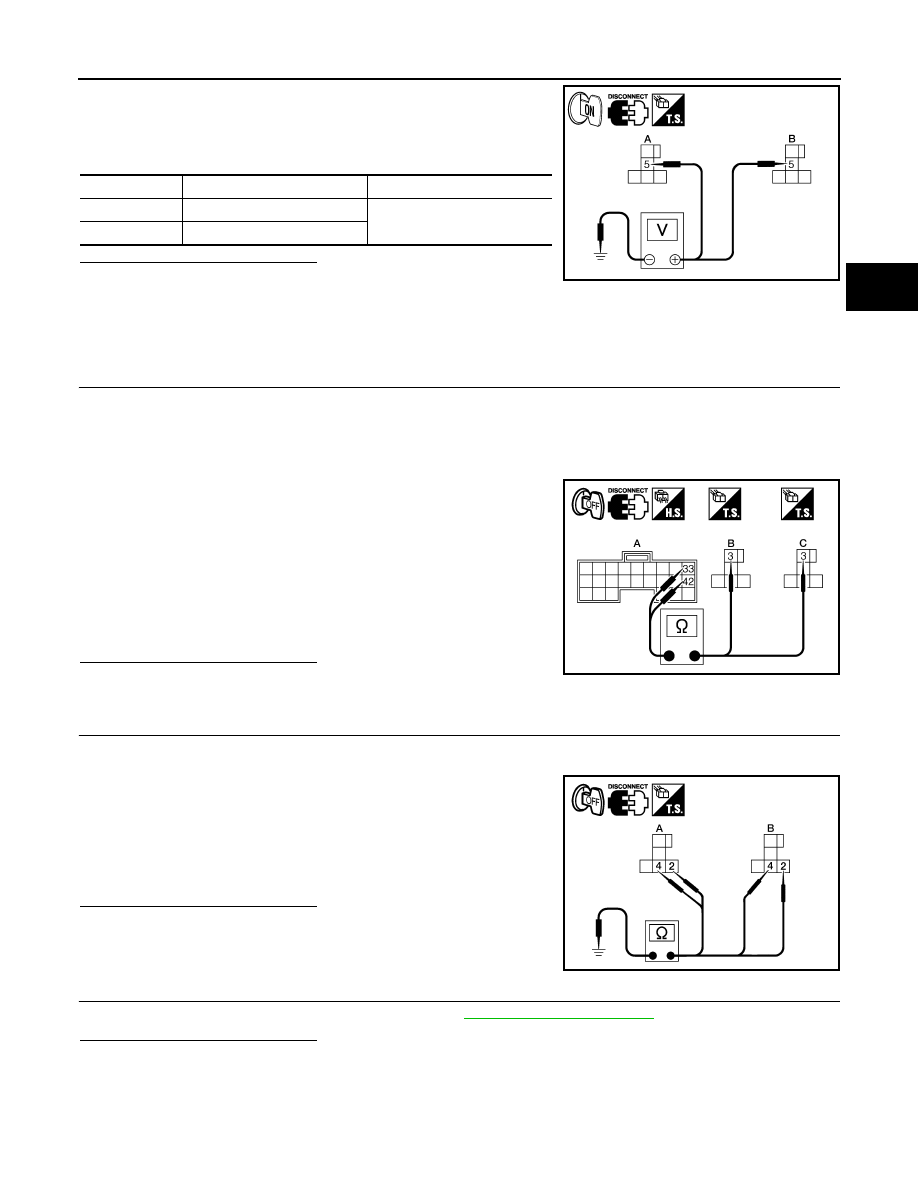
4. Turn ignition switch ON. (Do not start engine.)
5. Check voltage between transfer shift high relay harness connec-
tor E46 terminal 5 (A), transfer shift low relay harness connector
E47 terminal 5 (B) and ground.
Are the inspection results normal?
YES
>> GO TO 4.
NO
>> Check the following. If any items are damaged, repair or replace damaged parts.
• 20A fuse (No. 57 located in the fuse and relay box).
• Harness for short or open between battery, transfer shift high relay harness connector E46 ter-
minal 5 and transfer shift low relay harness connector E47 terminal 5.
4.
CHECK HARNESS BETWEEN TRANSFER CONTROL UNIT AND TRANSFER SHIFT RELAY
1. Turn ignition switch OFF. (Stay for at least 5 seconds.)
2. Disconnect transfer control unit harness connector and transfer control device (actuator motor) harness
connector.
3. Remove transfer shift high relay and transfer shift low relay.
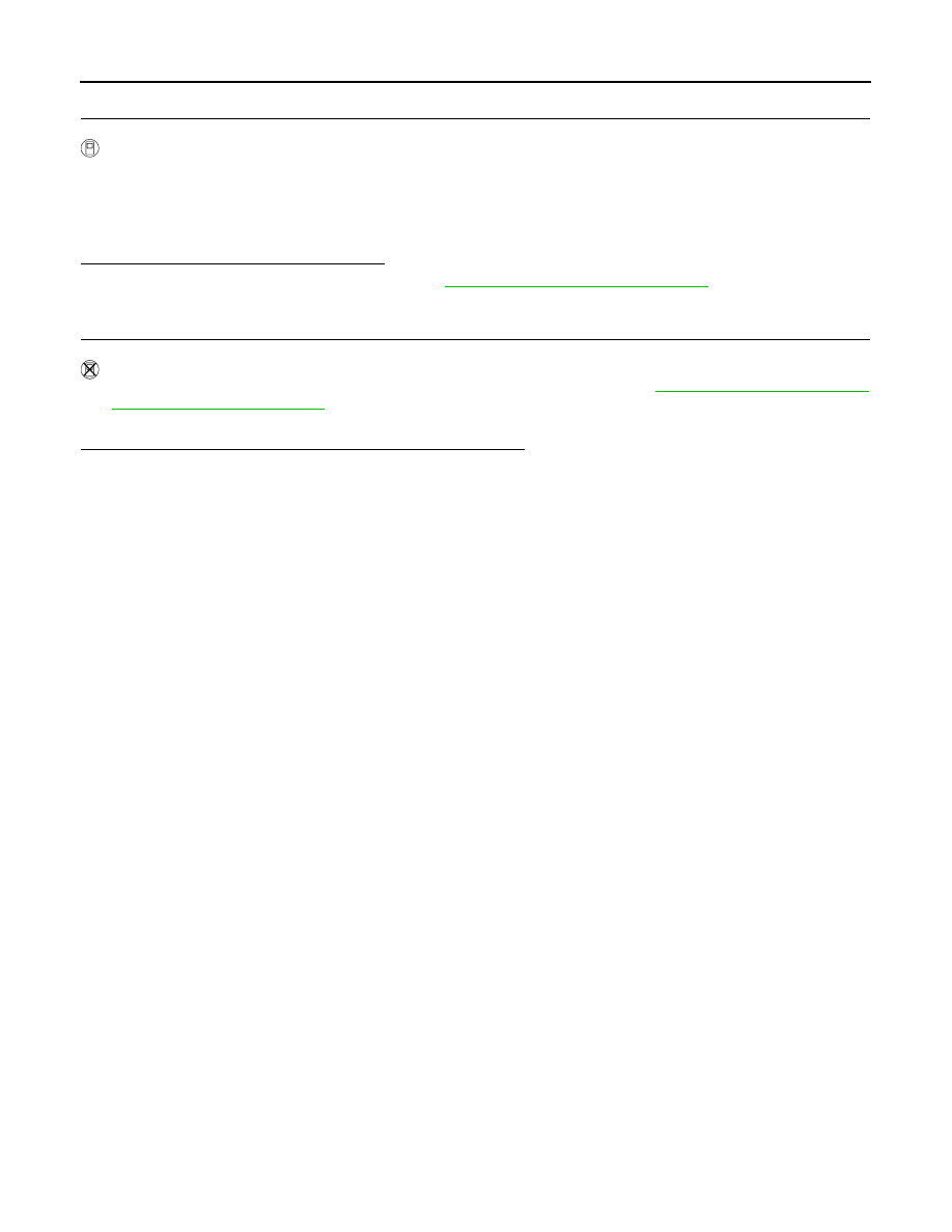
4. Check continuity between the following terminals.
-
Transfer control unit harness connector E143 (A) terminal 33
and transfer shift high relay harness connector E46 (B) terminal
3.
-
Transfer control unit harness connector E143 (A) terminal 42
and transfer shift low relay harness connector E47 (C) terminal
3.
Also check harness for short to ground and short to power.
Are the inspection results normal?
YES
>> GO TO 5.
NO
>> Repair or replace damaged parts.
5.
CHECK TRANSFER SHIFT RELAY GROUND CIRCUIT
1. Turn ignition switch OFF. (Stay for at least 5 seconds.)
2. Remove transfer shift high relay and transfer shift low relay.
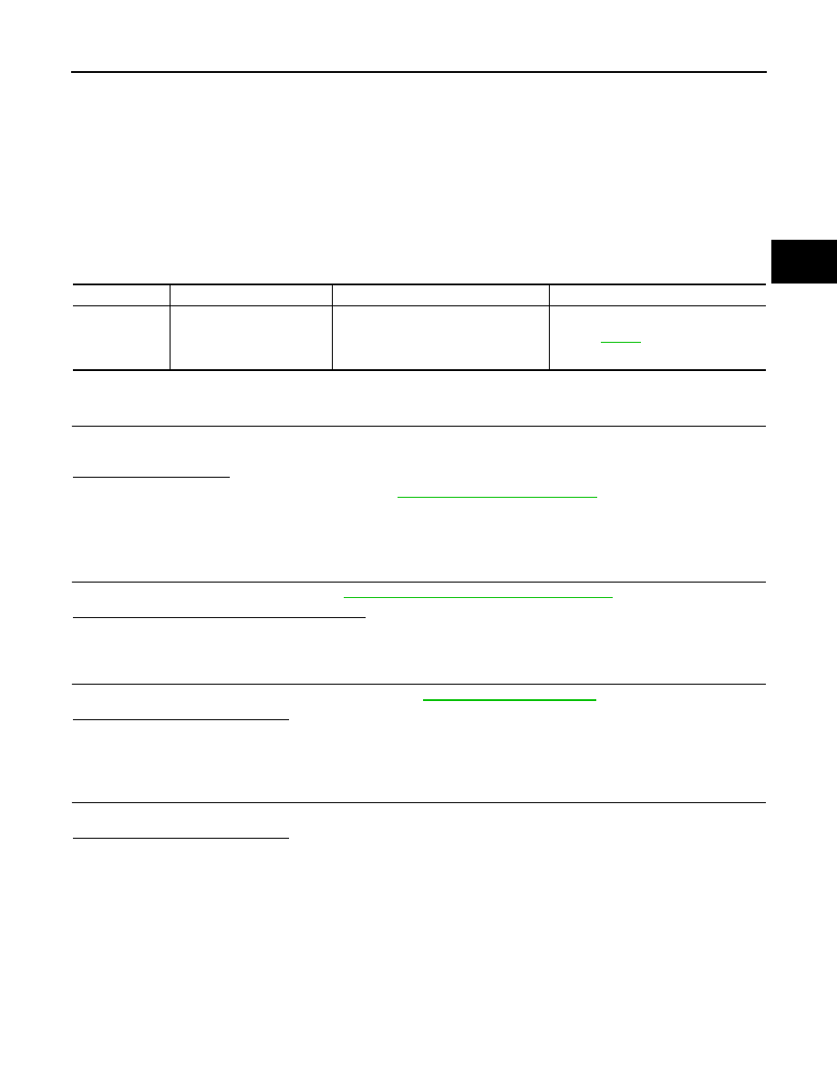
3. Check continuity between transfer shift high relay harness con-
nector E46 (A) terminals 2, 4, transfer shift low relay harness
connector E47 (B) terminals 2, 4 and ground.
Also check harness for short to ground and short to power.
Are the inspection results normal?
YES
>> GO TO 6.
NO
>> Repair open circuit or short to ground or short to power
in harness or connectors.
6.
CHECK TRANSFER CONTROL UNIT
Check transfer control unit input/output signal. Refer to
Are the inspection results normal?
YES-1 >> With CONSULT-III: GO TO 7.
YES-2 >> Without CONSULT-III: GO TO 8.
NO
>> Check transfer control unit pin terminals for damage or loose connection with harness connector.
If any items are damaged, repair or replace damaged parts.
Connector
Terminal
Voltage (Approx.)
A: E46
5 - Ground
Battery voltage
B: E47
5 - Ground
WDIA0311E
Continuity should exist.
WDIA0315E
Continuity should exist.
WDIA0312E
DLN-52
< COMPONENT DIAGNOSIS >
[ATX14B]
P1819 TRANSFER CONTROL DEVICE
7.
PERFORM SELF-DIAGNOSIS (WITH CONSULT-III)
With CONSULT-III
1. Turn ignition switch ON. (Do not start engine.)
2. Select SELF-DIAG RESULTS mode for ALL MODE AWD/4WD with CONSULT-III.
3. Touch ERASE.
4. Turn ignition switch OFF and wait at least 10 seconds.
5. Perform the self-diagnosis again.
Is the SHIFT ACT CIR [P1819] displayed?
YES
>> Replace transfer control unit. Refer to
DLN-130, "Removal and Installation"
.
NO
>> Inspection End.
8.
PERFORM SELF-DIAGNOSIS (WITHOUT CONSULT-III)
Without CONSULT-III
1. Perform the self-diagnosis and then erase self-diagnostic results. Refer to
2. Perform the self-diagnosis again.
Do the self-diagnostic results indicate transfer control device?
YES
>> Replace transfer control unit.
NO
>> Inspection End.
P1820 ENGINE SPEED SIGNAL
DLN-53
< COMPONENT DIAGNOSIS >
[ATX14B]
C
E
F
G
H
I
J
K
L
M
A
B
DLN
N
O
P
P1820 ENGINE SPEED SIGNAL
Description
INFOID:0000000005148814
The ECM transmits the engine speed signal via CAN communication to the transfer control unit. DTC P1820
will set when either of the following occur:
• Malfunction is detected in engine speed signal that is output from the ECM.
• Improper signal is input while driving.
DTC Logic
INFOID:0000000005148815
DTC DETECTION LOGIC
DTC CONFIRMATION PROCEDURE
1.
DTC CONFIRMATION PROCEDURE
1. Turn ignition switch ON.
2. Perform self-diagnosis.
Is DTC P1820 detected?
YES
>> Perform diagnosis procedure. Refer to
.
NO
>> Inspection End.
Diagnosis Procedure
INFOID:0000000005148816
1.
CHECK DTC WITH ECM
Perform self-diagnosis with ECM. Refer to
EC-63, "CONSULT-III Function (ENGINE)"
.
Is any malfunction detected by self-diagnosis?
YES
>> Check the malfunctioning system.
NO
>> GO TO 2.
2.
CHECK TRANSFER CONTROL UNIT
Check transfer control unit input/output signal. Refer to
Are the inspection results normal?
YES
>> GO TO 3.
NO
>> Check transfer control unit pin terminals for damage or loose connection with harness connector.
If any items are damaged, repair or replace damaged parts.
3.
CHECK DTC
Drive the vehicle and then perform self-diagnosis.
Are the inspection results normal?
YES
>> Inspection End.
NO
>> Perform self-diagnosis with ECM again.
DTC
CONSULT-III
Diagnostic item is detected when...
Reference
[P1820]
ENGINE SPEED SIG
• Malfunction is detected in engine
speed signal that is output from ECM
through CAN communication.
• Improper signal is input while driving.
DLN-54
< COMPONENT DIAGNOSIS >
[ATX14B]
P1822 CLUTCH PRESSURE SOLENOID
P1822 CLUTCH PRESSURE SOLENOID
Description
INFOID:0000000005148817
Proper voltage is not applied to the clutch pressure solenoid valve due to open or short circuit.
DTC Logic
INFOID:0000000005148818
DTC DETECTION LOGIC
DTC CONFIRMATION PROCEDURE
1.
DTC CONFIRMATION PROCEDURE
1. Turn ignition switch ON.
2. Perform self-diagnosis.
Is DTC P1822 displayed?
YES
>> Perform diagnosis procedure. Refer to
.
NO
>> Inspection End.
Diagnosis Procedure
INFOID:0000000005148819
Regarding Wiring Diagram information, refer to
DLN-89, "Wiring Diagram - ALL-MODE 4WD SYSTEM -"
.
1.
CHECK CLUTCH PRESSURE SIGNAL
With CONSULT-III
1. Start engine.
2. Select DATA MONITOR mode for ALL MODE AWD/4WD with CONSULT-III.
3. Read out the value of DUTY SOLENOID.
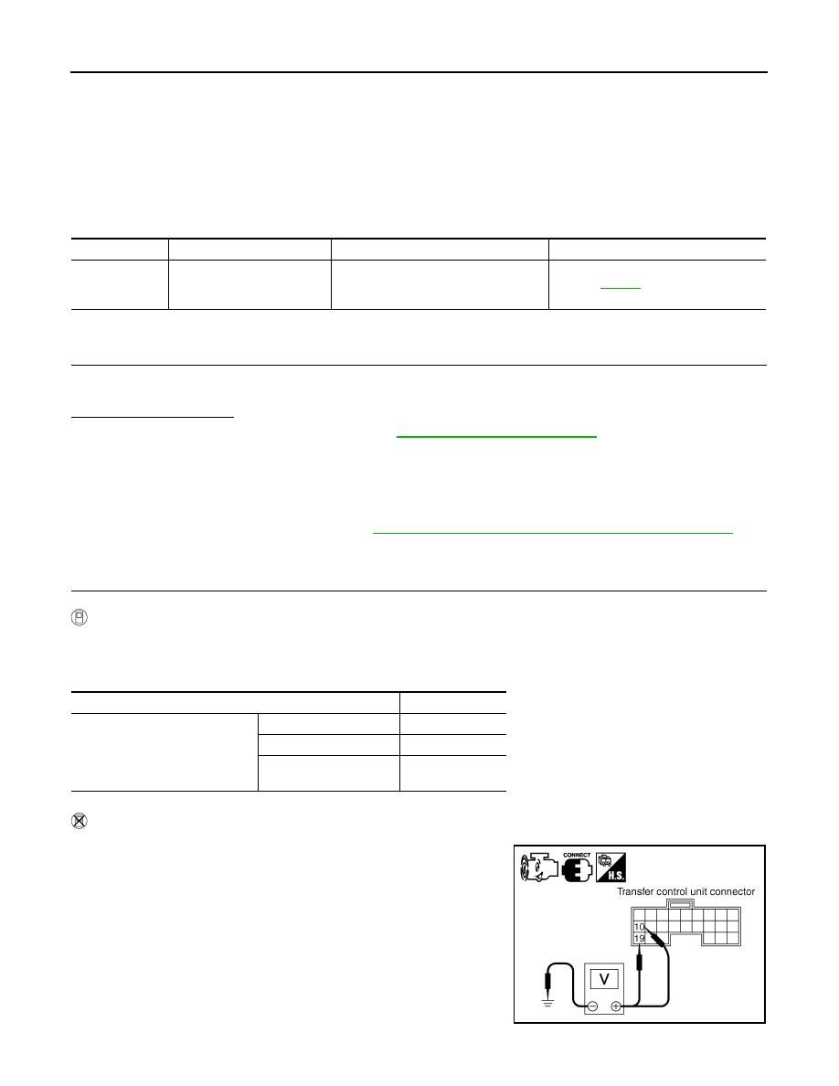
Without CONSULT-III
1. Start engine.
2. Check voltage between transfer control unit harness connector
terminal and ground.
DTC
CONSULT-III
Diagnostic item is detected when...
Reference
[P1822]
DUTY SOLENOID
Proper voltage is not applied to clutch
pressure solenoid valve due to open or
short circuit.
Refer to
.
Condition
Display value
• Vehicle stopped
• Engine running
• A/T selector lever N position
• Brake pedal depressed
4WD shift switch: 2WD
4%
4WD shift switch: AUTO
96 - 4%
4WD shift switch: 4H or
4LO
4%
SDIA2719E
Нет комментариевНе стесняйтесь поделиться с нами вашим ценным мнением.
Текст