Infiniti QX56 (JA60). Manual — part 57
AV-36
< FUNCTION DIAGNOSIS >
[AUDIO SYSTEM]
DIAGNOSIS SYSTEM (AV CONTROL UNIT)
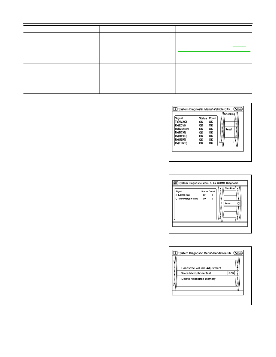
Vehicle CAN Diagnosis
• CAN communication status and error counter is displayed.
• The error counter displays “OK” if any malfunction was not
detected in the past and displays “0” if a malfunction is detected. It
increases by 1 if the condition is normal at the next ignition switch
ON cycle. The upper limit of the counter is 39.
• The error counter is erased if reset.
AV COMM Diagnosis
• AV communication status and error counter is displayed.
• The error counter displays “OK” if any malfunction was not
detected in the past and displays “0” if a malfunction is detected. It
increases by 1 if the condition is normal at the next ignition switch
ON cycle. The upper limit of the counter is 39.
• The error counter is erased if reset.
Handsfree Phone
The hands-free phone reception volume adjustment, microphone
and speaker test, and memory erase functions are also available.
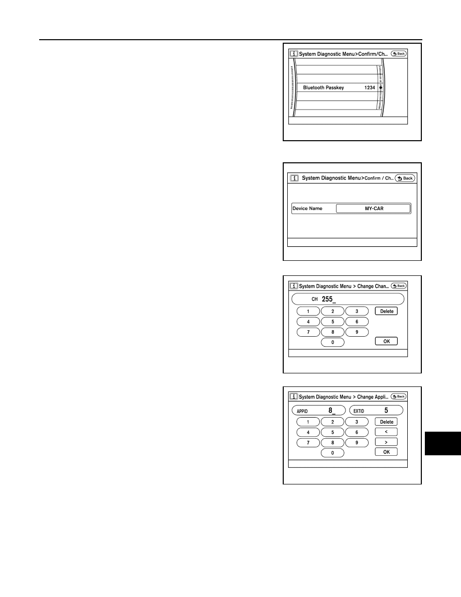
Bluetooth
Passkey confirmation/change
• AV COMM CIRCUIT
• Rear View Camera Connection Error
• A malfunction is detected in camera con-
trol unit power supply and ground cir-
cuits.
• Malfunction is detected on AV communi-
cation signal between camera control
unit and AV control unit.
Rear view camera control unit power sup-
ply and ground circuits. Refer to
"REAR VIEW CAMERA CONTROL UNIT :
Diagnosis Procedure"
• AV COMM CIRCUIT
• Rear View Camera Connection Error
• Rear View Camera Control Unit Connec-
tion Error
• Malfunction is detected in AV communi-
cation circuit between camera control
unit and AV control unit.
• Malfunction is detected on AV communi-
cation signal between camera control
unit and AV control unit.
AV communication circuit between Camera
control unit and AV control unit.
Error item
Description
Possible malfunction factor/Action to take
ALNIA0227GB
ALNIA0265GB
ALNIA0228GB
AV
DIAGNOSIS SYSTEM (AV CONTROL UNIT)
AV-37
< FUNCTION DIAGNOSIS >
[AUDIO SYSTEM]
C
D
E
F
G
H
I
J
K
L
M
B
A
O
P
• The passkey of Bluetooth can be confirmed and changed.
• The passkey can be changed by four digits within 0 to 9.
Device name check/change
• The device name of Bluetooth can be confirmed and changed.
• The device name can be changed by sixteen digits within A to Z
(small character can be used) and - (hyphen).
SAT
• Change Channel
- Any necessary channels required to receive traffic information from
the satellite radio system can be set.
• Change Application ID
- Any application ID's required to receive traffic information from the
satellite radio system can be set.
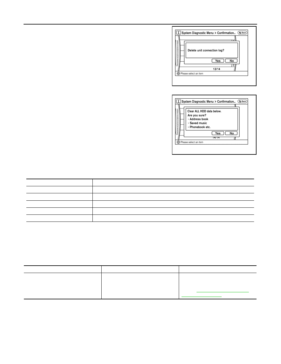
Delete Unit Connection Log
ALNIA0233GB
AWNIA1553GB
ALNIA0236GB
ALNIA0237GB
AV-38
< FUNCTION DIAGNOSIS >
[AUDIO SYSTEM]
DIAGNOSIS SYSTEM (AV CONTROL UNIT)
Deletes any unit connection records and error records from the AV
control unit memory. (Clear the records of the unit that has been
removed)
Inititialize Settings
Initializes the AV control unit memory.
AV CONTROL UNIT : CONSULT-III Function
INFOID:0000000005146243
CONSULT-III can display each diagnostic item using the diagnostic test modes shown following.
Self-diagnosis results
• In CONSULT-III self-diagnosis, self-diagnosis results and error history are displayed collectively.
• The current malfunction indicates “CRNT”. The past malfunction indicates “PAST”.
• The timing is displayed as “0” if any of the error codes [U1000], [U1010], [U1300] and [U1310] is detected.
The counter increases by 1 if the condition is normal at the next ignition switch ON cycle.
Self-diagnosis results display item
ALNIA0239GB
ALNIA0240GB
MULTI AV diagnosis mode
Description
SELF-DIAG RESULTS
Displays AV control unit self-diagnosis results.
DATA MONITOR
Displays AV control unit input/output data in real time.
CAN DIAG SUPPORT MNTR
The result of transmit/receive diagnosis of CAN communication can be read.
AV COMM MONITOR
Allows the technician to monitor the status of the Multi AV system communication signals.
ECU PART NUMBER
The part number of AV control unit can be checked.
Error item
Description
Possible malfunction factor/Action to take
CAN COMM CIRCUIT[U1000]
CAN communication malfunction is detect-
ed.
Perform diagnosis with CONSULT-III, and
then repair the malfunctioning parts accord-
ing to the diagnosis results.
Refer to

AV
DIAGNOSIS SYSTEM (AV CONTROL UNIT)
AV-39
< FUNCTION DIAGNOSIS >
[AUDIO SYSTEM]
C
D
E
F
G
H
I
J
K
L
M
B
A
O
P
CONTROL UNIT (CAN) [U1010]
CAN initial diagnosis malfunction is detect-
ed.
Replace the AV control unit. Refer to
169, "Removal and Installation"
.
CONTROL UNIT (AV) [U1310]
AV communication circuit initial diagnosis
malfunction is detected.
Control Unit FLASH-ROM [U1200]
AV control unit malfunction is detected.
Gyro NO CONN [U1201]
CAN CONT [U1216]
BLUETOOTH CONN [U1217]
HDD CONN [U1218]
HDD READ [U1219]
XM SERIAL COMM [U1220]
HDD WRITE [U121A]
HDD COMM [U121B]
HDD ACCESS [U121C]
DSP CONN [U121D]
DSP COMM [U121E]
INTERNAL COMM [U121F]
AV control unit power supply and ground
circuit. Refer to
GPS COMM [U1204]
GPS malfunction is detected.
An intermittent error caused by strong radio
interference may be detected unless any
symptoms (GPS reception error, etc.) oc-
cur.
Replace the AV control unit if the malfunc-
tion occurs constantly. Refer to
GPS ROM [U1205]
GPS RAM [U1206]
GPS RTC [U1207]
FRONT DISP CONN [U1243]
• Display unit power supply and ground
circuit malfunction is detected.
• Malfunction is detected on communica-
tion circuit between display unit and AV
control unit.
• Malfunction is detected on communica-
tion signal between display unit and AV
control unit.
• Display unit power supply and ground
.
• Communication circuit between display
unit and AV control unit. Refer to
.
GPS ANTENNA CONN [U1244]
GPS antenna connection malfunction is de-
tected.
GPS antenna. Refer to
.
XM ANTENNA CONN [U1258]
Poor connection is detected in satellite ra-
dio antenna.
Satellite radio antenna. Refer to
CAMERA CONT. CONN [U1250]
A malfunction is detected in Camera-con-
nection recognition signal circuit.
Camera-connection recognition signal cir-
cuit. Refer to
.
• AV COMM CIRCUIT [U1300]
• SWITCHE CONN [U1240]
• AC and AV switch power supply and
ground circuit malfunction is detected.
• A malfunction is detected in AV commu-
nication circuit between AV control unit
and AC and AV switch.
• A malfunction is detected in AV commu-
nication signal between AV control unit
and AC and AV switch.
• AC and AV switch power supply and
ground circuits. Refer to
AND AV SWITCH ASSEMBLY : Diagno-
sis Procedure"
• AV communication circuit between AV
control unit and AC and AV switch. Refer
to
.
Error item
Description
Possible malfunction factor/Action to take
Нет комментариевНе стесняйтесь поделиться с нами вашим ценным мнением.
Текст