Infiniti QX56 (JA60). Manual — part 58
AV-40
< FUNCTION DIAGNOSIS >
[AUDIO SYSTEM]
DIAGNOSIS SYSTEM (AV CONTROL UNIT)
DATA MONITOR
Display Item List
A/C AND AV SWITCH ASSEMBLY
A/C AND AV SWITCH ASSEMBLY : Component Function Check
INFOID:0000000005146244
A/C and AV switch assembly self-diagnosis function
Description
The ON/OFF operation (continuity) of each switch in the A/C and AV switch assembly can be checked.
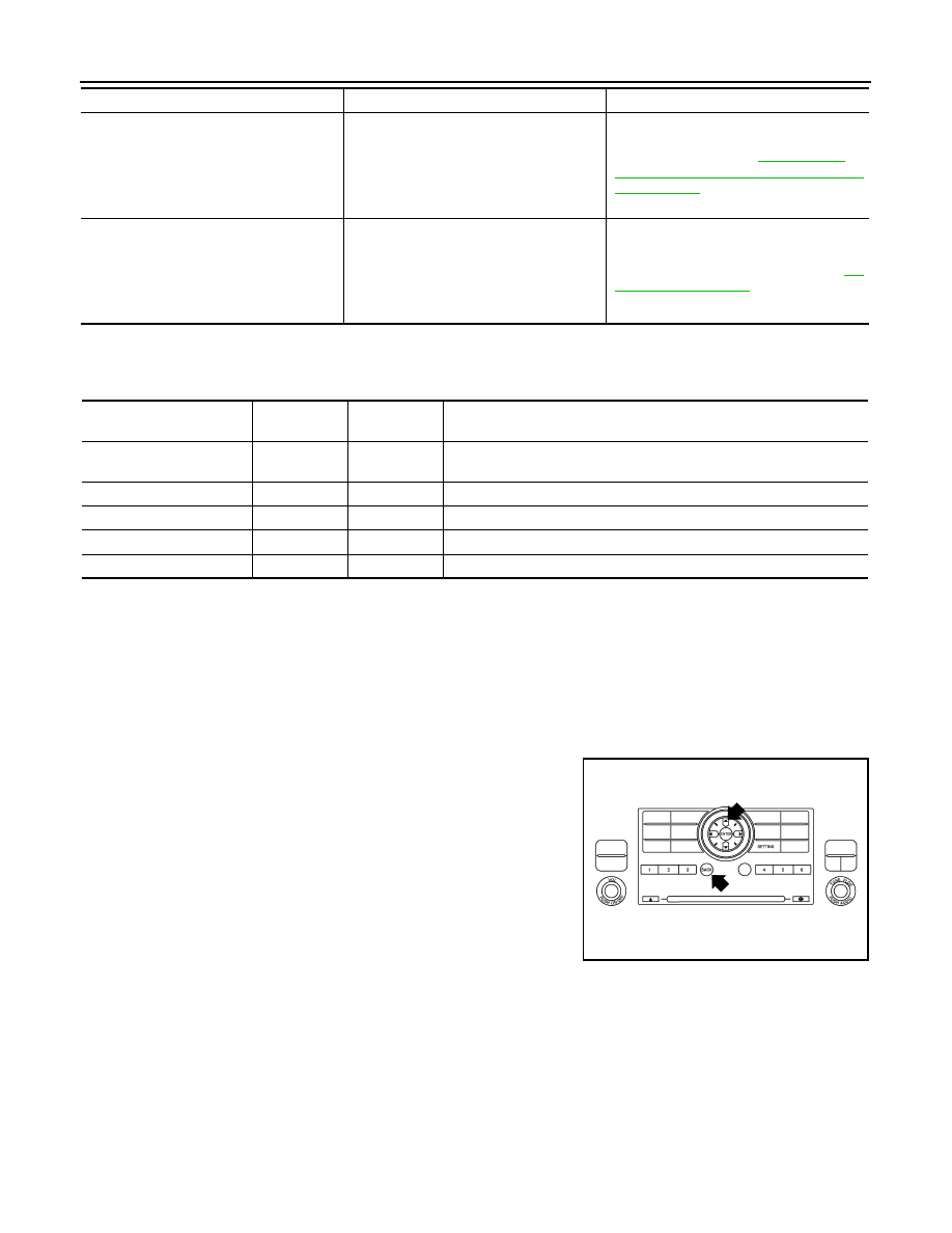
Self-diagnosis mode
• Press the “BACK” button and the “UP” button within 10 seconds
after turning the ignition switch from OFF to ACC and hold them for
3 seconds or more. When the self-diagnosis mode starts, a beep
will sound and all LED indicators of the switch will illuminate.
• The continuity of each switch and control dial of the A/C and AV
switch assembly can be checked. If the switch is operating nor-
mally, the system will beep and the LED’s will illuminate when each
switch is operated.
Finishing self-diagnosis mode
Self-diagnosis mode is canceled when the ignition switch is turned OFF.
• AV COMM CIRCUIT [U1300]
• REAR CAMERA LAN CONN [U1252]
• A malfunction is detected in camera con-
trol unit power supply and ground cir-
cuits.
• Malfunction is detected on AV communi-
cation signal between Camera control
unit and AV control unit.
Camera control unit power supply and
ground circuits. Refer to
VIEW CAMERA CONTROL UNIT : Diagno-
sis Procedure"
.
• AV COMM CIRCUIT [U1300]
• CAMERA CONT. CONN [U1250]
• REAR CAMERA LAN CONN [U1252]
• Malfunction is detected on AV communi-
cation circuit between camera control
unit and AV control unit.
• Malfunction is detected on AV communi-
cation signal between camera control
unit and AV control unit.
AV communication circuit between camera
control unit and AV control unit. Refer to
.
Error item
Description
Possible malfunction factor/Action to take
Display item [unit]
ALL
SIGNALS
SELECTION
FROM MENU
Description
VHCL SPD SIG [ON/OFF]
X
X
Displays “ON” when vehicle speed > 0 km/h. Displays “OFF” when ve-
hicle speed = 0 km/h.
PKB SIG [ON/OFF]
X
X
Displays [ON/OFF] condition of parking brake switch.
ILLUM SIG [ON/OFF]
X
X
Displays [ON/OFF] condition of lighting switch.
IGN SIG [ON/OFF]
X
X
Displays [ON/OFF] condition of ignition switch.
REV SIG [ON/OFF]
X
X
Displays [ON/OFF] condition of back-up lamp switch.
AWIIA0171GB

AV
U1000 CAN COMM CIRCUIT
AV-41
< COMPONENT DIAGNOSIS >
[AUDIO SYSTEM]
C
D
E
F
G
H
I
J
K
L
M
B
A
O
P
COMPONENT DIAGNOSIS
U1000 CAN COMM CIRCUIT
Description
INFOID:0000000005146245
CAN (Controller Area Network) is a serial communication line for real time application. It is an on-vehicle mul-
tiplex communication line with high data communication speed and excellent error detection ability. Many elec-
tronic control units are equipped onto a vehicle and each control unit shares information and links with other
control units during operation (not independent). In CAN communication, control units are connected with 2
communication lines (CAN-H, CAN-L) allowing a high rate of information transmission with less wiring. Each
control unit transmits/receives data but selectively reads required data only.
CAN Communication Signal Chart. Refer to
LAN-44, "CAN Communication Signal Chart"
DTC Logic
INFOID:0000000005146246
DTC DETECTION LOGIC
Diagnosis Procedure
INFOID:0000000005146247
1.
PERFORM SELF DIAGNOSTIC
1. Turn ignition switch ON and wait for 2 seconds or more.
2. Check “Self Diagnostic Result” of “AV Control Unit”.
Is “CAN COMM CIRCUIT” displayed?
YES
>> Refer to “LAN system”. Refer to
LAN-14, "Trouble Diagnosis Flow Chart"
NO
>> Refer to GI section. Refer to
GI-38, "Intermittent Incident"
.
DTC
Display contents of CON-
SULT-III
Diagnostic item is detected when ...
Probable malfunction location
U1000
CAN COMM CIRCUIT
When AV control unit is not transmitting or re-
ceiving CAN communication signal for 2 sec-
onds or more.
CAN communication system.
AV-42
< COMPONENT DIAGNOSIS >
[AUDIO SYSTEM]
U1010 CONTROL UNIT (CAN)
U1010 CONTROL UNIT (CAN)
Description
INFOID:0000000005146248
Initial diagnosis of AV control unit.
DTC Logic
INFOID:0000000005146249
DTC DETECTION LOGIC
Diagnosis Procedure
INFOID:0000000005146250
1.
REPLACE AV CONTROL UNIT
When DTC U1010 is detected, replace AV control unit. Refer to
AV-169, "Removal and Installation"
.
>> Inspection end.
DTC
Display contents of CON-
SULT-III
Diagnostic item is detected when ...
Probable malfunction location
U1010
CONTROL UNIT (CAN)
CAN initial diagnosis malfunction is detected.
AV control unit.
AV
U1200 AV CONTROL UNIT
AV-43
< COMPONENT DIAGNOSIS >
[AUDIO SYSTEM]
C
D
E
F
G
H
I
J
K
L
M
B
A
O
P
U1200 AV CONTROL UNIT
Description
INFOID:0000000005146251
Replace the AV control unit if this DTC is displayed. Refer to
AV-169, "Removal and Installation"
.
DTC Logic
INFOID:0000000005146252
Part name
Description
AV CONTROL UNIT
• It is the master unit of the MULTI AV system and it is connected to each control
unit by means of communication. It operates each system according to com-
munication signals from the AV control unit.
• AV control unit includes audio function and vehicle information function.
• It is connected to ECM and combination meter via CAN communication to ob-
tain necessary information for the vehicle information function.
• It inputs the automatic brightness ON/OFF signals that are required for the dis-
play dimming control.
• It inputs the signals for driving status recognition (vehicle speed, reverse and
parking brake).
DTC
Display contents of CONSULT-III
DTC Detection Condition
Action to take
U1200
Control Unit
FLASH- ROM
[U1200]
An internal malfunction is detected in AV control unit
(FLASH-ROM).
Replace AV control unit. Re-
fer to
.
Нет комментариевНе стесняйтесь поделиться с нами вашим ценным мнением.
Текст