Infiniti QX56 (JA60). Manual — part 604
WATER VALVE CIRCUIT
HAC-73
< COMPONENT DIAGNOSIS >
[AUTOMATIC AIR CONDITIONER]
C
D
E
F
G
H
J
K
L
M
A
B
HAC
N
O
P
WATER VALVE CIRCUIT
Description
INFOID:0000000005147716
COMPONENT DESCRIPTION
Water Valve
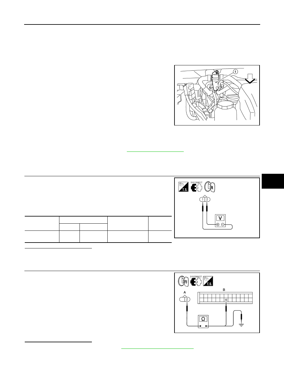
The water valve (1) cuts the flow of engine coolant to the front and
rear heater cores to allow for maximum cooling during A/C opera-
tion. It is controlled by the A/C auto amp.
Water Valve Diagnosis Procedure
INFOID:0000000005147717
Regarding Wiring Diagram information, refer to
DIAGNOSTIC PROCEDURE FOR WATER VALVE
1.
CHECK WATER VALVE POWER AND GROUND CIRCUITS
1. Disconnect water valve connector F68.
2. Turn ignition switch ON.
3. Rotate temperature control dial (driver) to 32
°C (90°F).
4. Check voltage between water valve harness connector F68 ter-
minal 1 and terminal 2 while rotating temperature control dial
(driver) to 18
°C (60°F).
Is the inspection result normal?
YES
>> GO TO 3.
NO
>> GO TO 2.
2.
CHECK WATER VALVE CONTROL OUTPUT CIRCUIT
1. Turn ignition switch OFF.
2. Disconnect A/C auto amp. connector M50.
3. Check continuity between water valve harness connector F68
(A) terminal 2 and A/C auto amp. harness connector M50 (B)
terminal 46.
4. Check continuity between water valve harness connector F68
terminal 2 and ground.
Is the inspection result normal?
YES
>> Replace A/C auto amp. Refer to
VTL-7, "Removal and Installation"
.
NO
>> Repair harness or connector.
WJIA1791E
Connector
Terminals
Condition
Voltage
(Approx.)
(+) (-)
Water valve: F68
2
1
Rotate temperature
control dial
Battery
voltage
WJIA1794E
2 - 46
: Continuity should exist.
2 - Ground
: Continuity should not exist.
AWIIA0203ZZ
HAC-74
< COMPONENT DIAGNOSIS >
[AUTOMATIC AIR CONDITIONER]
WATER VALVE CIRCUIT
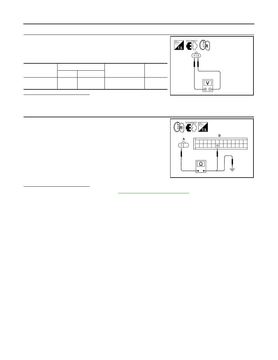
3.
CHECK WATER VALVE POWER AND GROUND CIRCUITS
1. Rotate temperature control dial (driver) to 18
°C (60°F).
2. Check voltage between water valve harness connector F68 ter-
minal 1 and terminal 2 while rotating temperature control dial
(driver) to 32
°C (90°F).
Is the inspection result normal?
YES
>> Replace the water valve.
NO
>> GO TO 4.
4.
CHECK WATER VALVE CONTROL OUTPUT CIRCUIT
1. Turn ignition switch OFF.
2. Disconnect A/C auto amp. connector M50.
3. Check continuity between water valve harness connector F68
(A) terminal 1 and A/C auto amp. harness connector M50 (B)
terminal 45.
4. Check continuity between water valve harness connector F68
(A) terminal 1 and ground.
Is the inspection result normal?
YES
>> Replace A/C auto amp. Refer to
VTL-7, "Removal and Installation"
NO
>> Repair harness or connector.
Connector
Terminals
Condition
Voltage
(Approx.)
(+) (-)
Water valve: F68
1
2
Rotate temperature
control dial
Battery
voltage
WJIA1792E
1 - 45
: Continuity should exist.
1 - Ground
: Continuity should not exist.
AWIIA0204ZZ
AMBIENT SENSOR
HAC-75
< COMPONENT DIAGNOSIS >
[AUTOMATIC AIR CONDITIONER]
C
D
E
F
G
H
J
K
L
M
A
B
HAC
N
O
P
AMBIENT SENSOR
Component Description
INFOID:0000000005147718
COMPONENT DESCRIPTION
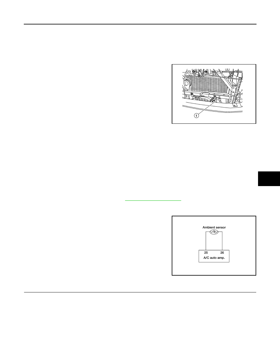
Ambient Sensor
The ambient sensor (1) is attached on the radiator core support (left
side). It detects ambient temperature and converts it into a value
which is then input into the A/C auto amp.
AMBIENT TEMPERATURE INPUT PROCESS
The A/C auto amp. includes a processing circuit for the ambient sensor input. However, when the temperature
detected by the ambient sensor increases quickly, the processing circuit retards the A/C auto amp. function. It
only allows the A/C auto amp. to recognize an ambient temperature increase of 0.33
°C (0.6°F) per 100 sec-
onds.
This prevents constant adjustments due to momentary conditions, such as stopping after high speed driving.
Although the actual ambient temperature has not changed, the temperature detected by the ambient sensor
will increase. This is because the heat from the engine compartment can radiate to the front grille area, loca-
tion of the ambient sensor.
Ambient Sensor Diagnosis Procedure
INFOID:0000000005147719
Regarding Wiring Diagram information, refer to
DIAGNOSTIC PROCEDURE FOR AMBIENT SENSOR
SYMPTOM: Ambient sensor circuit is open or shorted. (40 or 41 is
indicated on A/C auto amp. as a result of conducting the A/C auto
amp. self-diagnosis)
1.
CHECK VOLTAGE BETWEEN AMBIENT SENSOR AND GROUND
AWIIA0238ZZ
AWIIA0160GB
HAC-76
< COMPONENT DIAGNOSIS >
[AUTOMATIC AIR CONDITIONER]
AMBIENT SENSOR
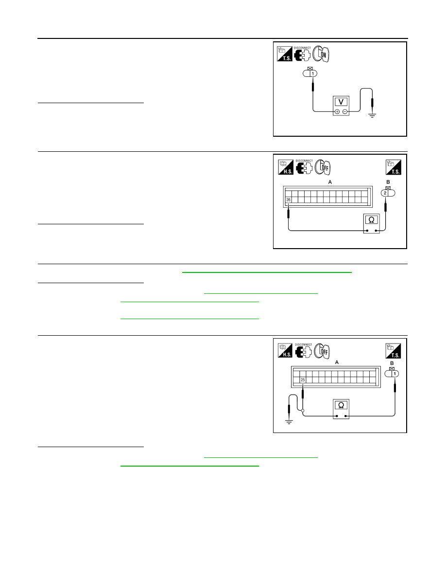
1. Disconnect ambient sensor connector.
2. Turn ignition switch ON.
3. Check voltage between ambient sensor harness connector E1
terminal 1 and ground.
Is the inspection result normal?
YES
>> GO TO 2.
NO
>> GO TO 4.
2.
CHECK CIRCUIT CONTINUITY BETWEEN AMBIENT SENSOR AND A/C AUTO AMP.
1. Turn ignition switch OFF.
2. Disconnect A/C auto amp. connector.
3. Check continuity between ambient sensor harness connector
E1 (B) terminal 2 and A/C auto amp. harness connector M49 (A)
terminal 26.
Is the inspection result normal?
YES
>> GO TO 3.
NO
>> Repair harness or connector.
3.
CHECK AMBIENT SENSOR
Check the ambient sensor circuit. Refer to
HAC-76, "Ambient Sensor Component Inspection"
Is the inspection result normal?
YES
>> 1. Replace A/C auto amp. Refer to
VTL-7, "Removal and Installation"
.
2. GO TO
HAC-23, "A/C Auto Amp. Self-Diagnosis"
and perform self-diagnosis.
NO
>> 1. Replace ambient sensor.
2. GO TO
HAC-23, "A/C Auto Amp. Self-Diagnosis"
and perform self-diagnosis.
4.
CHECK CIRCUIT CONTINUITY BETWEEN AMBIENT SENSOR AND A/C AUTO AMP.
1. Turn ignition switch OFF.
2. Disconnect A/C auto amp. connector.
3. Check continuity between ambient sensor harness connector
E1 (B) terminal 1 and A/C auto amp. harness connector M49 (A)
terminal 25.
4. Check continuity between ambient sensor harness connector
E1 (B) terminal 1 and ground.
Is the inspection result normal?
YES
>> 1. Replace A/C auto amp. Refer to
VTL-7, "Removal and Installation"
.
2. GO TO
HAC-23, "A/C Auto Amp. Self-Diagnosis"
and perform self-diagnosis.
NO
>> Repair harness or connector.
Ambient Sensor Component Inspection
INFOID:0000000005147720
COMPONENT INSPECTION
Ambient Sensor
1 - Ground
: Approx. 5V
AWIIA0161ZZ
2 - 26
: Continuity should exist.
AWIIA1039ZZ
1 - 25
: Continuity should exist.
1 - Ground
: Continuity should not exist.
AWIIA1040ZZ
Нет комментариевНе стесняйтесь поделиться с нами вашим ценным мнением.
Текст