Infiniti QX56 (JA60). Manual — part 605
AMBIENT SENSOR
HAC-77
< COMPONENT DIAGNOSIS >
[AUTOMATIC AIR CONDITIONER]
C
D
E
F
G
H
J
K
L
M
A
B
HAC
N
O
P
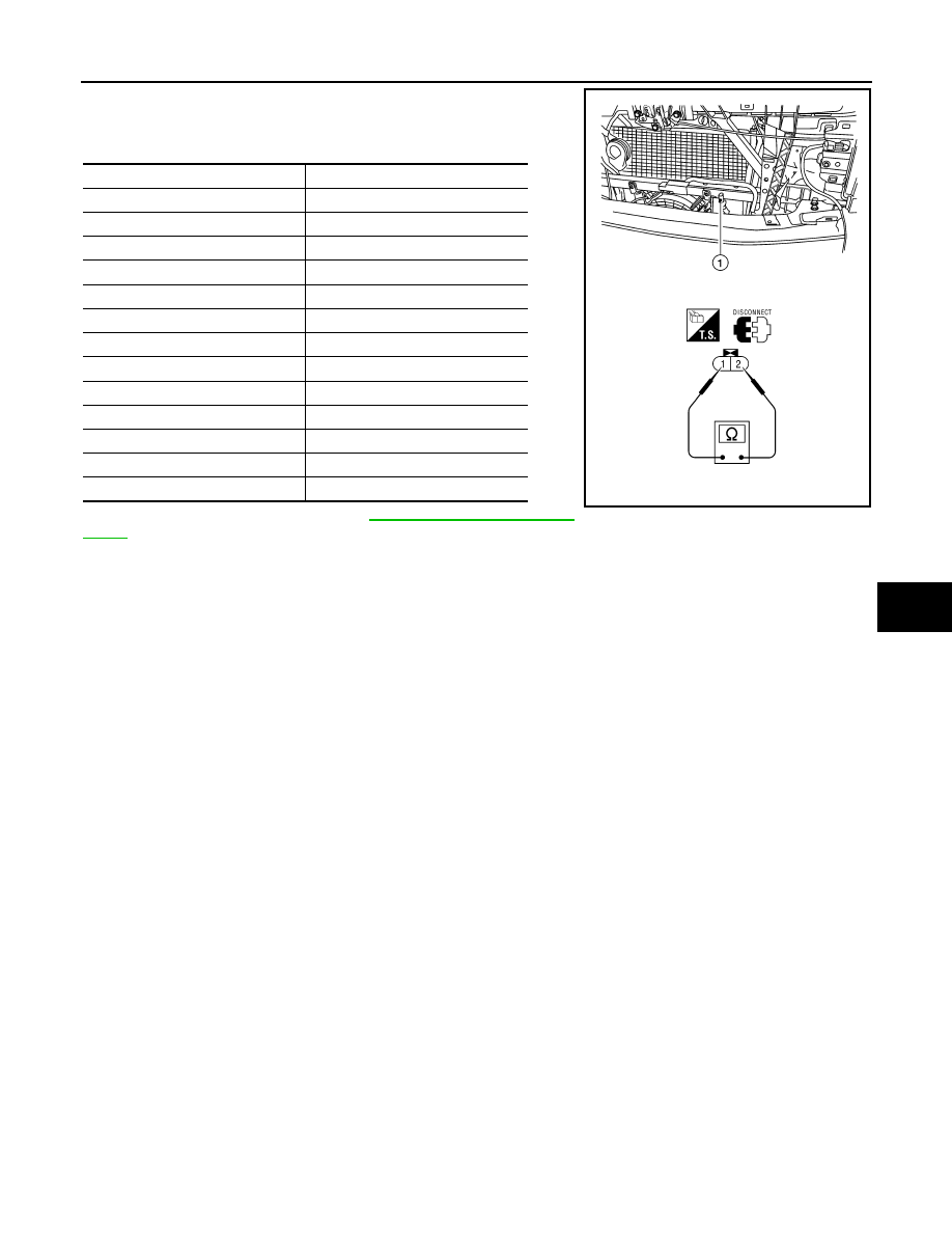
After disconnecting ambient sensor (1) connector E1, measure
resistance between terminals 1 and 2 at sensor component side,
using the table below.
If NG, replace ambient sensor. Refer to
.
Temperature
°C (°F)
Resistance k
Ω
−15 (5)
12.73
−10 (14)
9.92
−5 (23)
7.80
0 (32)
6.19
5 (41)
4.95
10 (50)
3.99
15 (59)
3.24
20 (68)
2.65
25 (77)
2.19
30 (86)
1.81
35 (95)
1.51
40 (104)
1.27
45 (113)
1.07
AWIIA0276ZZ
HAC-78
< COMPONENT DIAGNOSIS >
[AUTOMATIC AIR CONDITIONER]
IN-VEHICLE SENSOR
IN-VEHICLE SENSOR
Component Description
INFOID:0000000005147721
COMPONENT DESCRIPTION
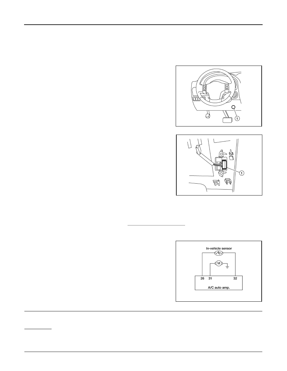
In-vehicle Sensor
The in-vehicle sensor (1) is located on the lower instrument panel
LH. It converts variations in temperature of passenger compartment
air (drawn in through the integrated fan) into a resistance value. It is
then input into the A/C auto amp.
In-Vehicle Sensor Diagnosis Procedure
INFOID:0000000005147722
Regarding Wiring Diagram information, refer to
DIAGNOSTIC PROCEDURE FOR IN-VEHICLE SENSOR
SYMPTOM: In-vehicle sensor circuit is open or shorted. Using the
CONSULT-III, DTC B2578 or B2579 is displayed. Without a CON-
SULT-III, code 30, 31, 44 or 46 is indicated on A/C auto amp. as a
result of conducting self-diagnosis.
1.
CHECK IN-VEHICLE SENSOR CIRCUIT
Is self-diagnosis DTC B2578 or B2579 (with CONSULT-III) or code 30, 31 44 or 46 (without CONSULT-III)
present?
YES or NO?
YES
>> GO TO 6.
NO
>> GO TO 2.
2.
CHECK VOLTAGE BETWEEN IN-VEHICLE SENSOR AND GROUND
AWIIA0815ZZ
AWIIA0165ZZ
AWIIA0166GB
IN-VEHICLE SENSOR
HAC-79
< COMPONENT DIAGNOSIS >
[AUTOMATIC AIR CONDITIONER]
C
D
E
F
G
H
J
K
L
M
A
B
HAC
N
O
P
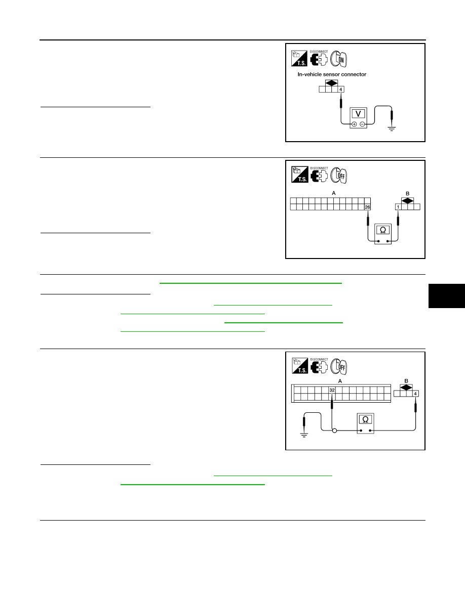
1. Disconnect in-vehicle sensor connector.
2. Turn ignition switch ON.
3. Check voltage between in-vehicle sensor harness connector
M32 terminal 4 and ground.
Is the inspection result normal?
YES
>> GO TO 3.
NO
>> GO TO 5.
3.
CHECK CIRCUIT CONTINUITY BETWEEN IN-VEHICLE SENSOR AND A/C AUTO AMP.
1. Turn ignition switch OFF.
2. Disconnect A/C auto amp. connector M49.
3. Check continuity between in-vehicle sensor harness connector
M32 (B) terminal 1 and A/C auto amp. harness connector M49
(A) terminal 26.
Is the inspection result normal?
YES
>> GO TO 4.
NO
>> Repair harness or connector.
4.
CHECK IN-VEHICLE SENSOR
Check in-vehicle sensor. Refer to
HAC-80, "In-Vehicle Sensor Component Inspection"
.
Is the inspection result normal?
YES
>> 1. Replace A/C auto amp. Refer to
VTL-7, "Removal and Installation"
.
2. Go to
HAC-23, "A/C Auto Amp. Self-Diagnosis"
and perform self-diagnosis.
NO
>> 1. Replace in-vehicle sensor. Refer to
VTL-9, "Removal and Installation"
.
2. Go to
HAC-23, "A/C Auto Amp. Self-Diagnosis"
and perform self-diagnosis.
5.
CHECK CIRCUIT CONTINUITY BETWEEN IN-VEHICLE SENSOR AND A/C AUTO AMP.
1. Turn ignition switch OFF.
2. Disconnect A/C auto amp. connector.
3. Check continuity between in-vehicle sensor harness connector
M32 (B) terminal 4 and A/C auto amp. harness connector M50
(A) terminal 32.
4. Check continuity between in-vehicle sensor harness connector
M32 (B) terminal 4 and ground.
Is the inspection result normal?
YES
>> 1. Replace A/C auto amp. Refer to
VTL-7, "Removal and Installation"
.
2. Go to
HAC-23, "A/C Auto Amp. Self-Diagnosis"
and perform self-diagnosis.
NO
>> Repair harness or connector.
6.
CHECK CIRCUIT CONTINUITY BETWEEN IN-VEHICLE SENSOR MOTOR AND A/C AUTO AMP. (SELF-
DIAGNOSIS CODES 30, 31, 44, 46 OR DTC B2578, B2579)
4 - Ground
: Approx. 5V.
LJIA0089E
1 - 26
: Continuity should exist.
AWIIA0167ZZ
4 - 32
: Continuity should exist.
4 - Ground
Continuity should not exist.
AWIIA0217ZZ
HAC-80
< COMPONENT DIAGNOSIS >
[AUTOMATIC AIR CONDITIONER]
IN-VEHICLE SENSOR
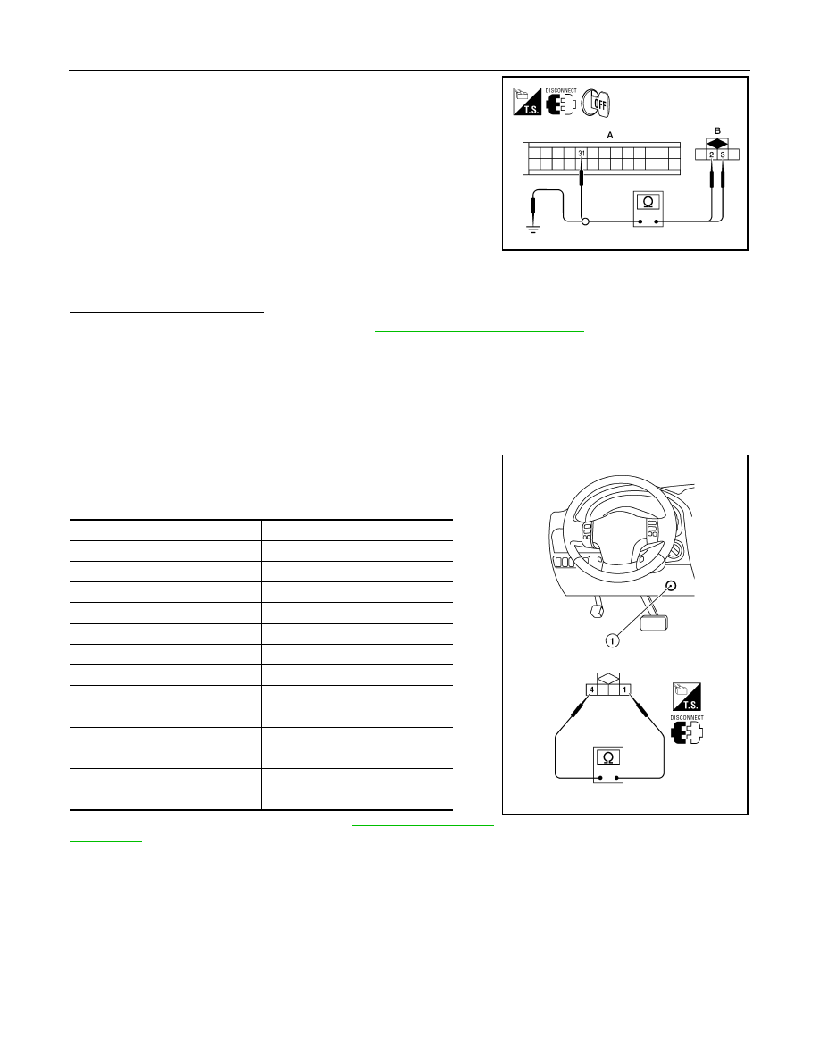
1. Turn ignition switch OFF.
2. Disconnect A/C auto amp. connector and in-vehicle sensor con-
nector.
3. Check continuity between in-vehicle sensor harness connector
M32 (B) terminal 3 and A/C auto amp. harness connector M50
(A) terminal 31.
4. Check continuity between in-vehicle sensor harness connector
M32 (B) terminal 3 and ground.
Is the inspection result normal?
YES
>> 1. Replace A/C auto amp. Refer to
VTL-7, "Removal and Installation"
.
2. Go to
HAC-23, "A/C Auto Amp. Self-Diagnosis"
and perform self-diagnosis.
NO
>> Repair harness or connector.
In-Vehicle Sensor Component Inspection
INFOID:0000000005147723
COMPONENT INSPECTION
In-vehicle Sensor
After disconnecting in-vehicle sensor connector M32, measure resis-
tance between terminals 1 and 4 at sensor component side, using
the table below.
If NG, replace in-vehicle sensor. Refer to
3 - 31
: Continuity should exist.
2 - Ground
: Continuity should exist.
3 - Ground
: Continuity should not exist.
AWIIA0168ZZ
Temperature
°C (°F)
Resistance k
Ω
−15 (5)
21.40
−10 (14)
16.15
−5 (23)
12.29
0 (32)
9.41
5 (41)
7.27
10 (50)
5.66
15 (59)
4.45
20 (68)
3.51
25 (77)
2.79
30 (86)
2.24
35 (95)
1.80
40 (104)
1.45
45 (113)
1.18
AWIIA0816ZZ
Нет комментариевНе стесняйтесь поделиться с нами вашим ценным мнением.
Текст