Infiniti QX56 (JA60). Manual — part 1000
DUCTS AND GRILLES
VTL-35
< ON-VEHICLE REPAIR >
C
D
E
F
G
H
J
K
L
M
A
B
VTL
N
O
P
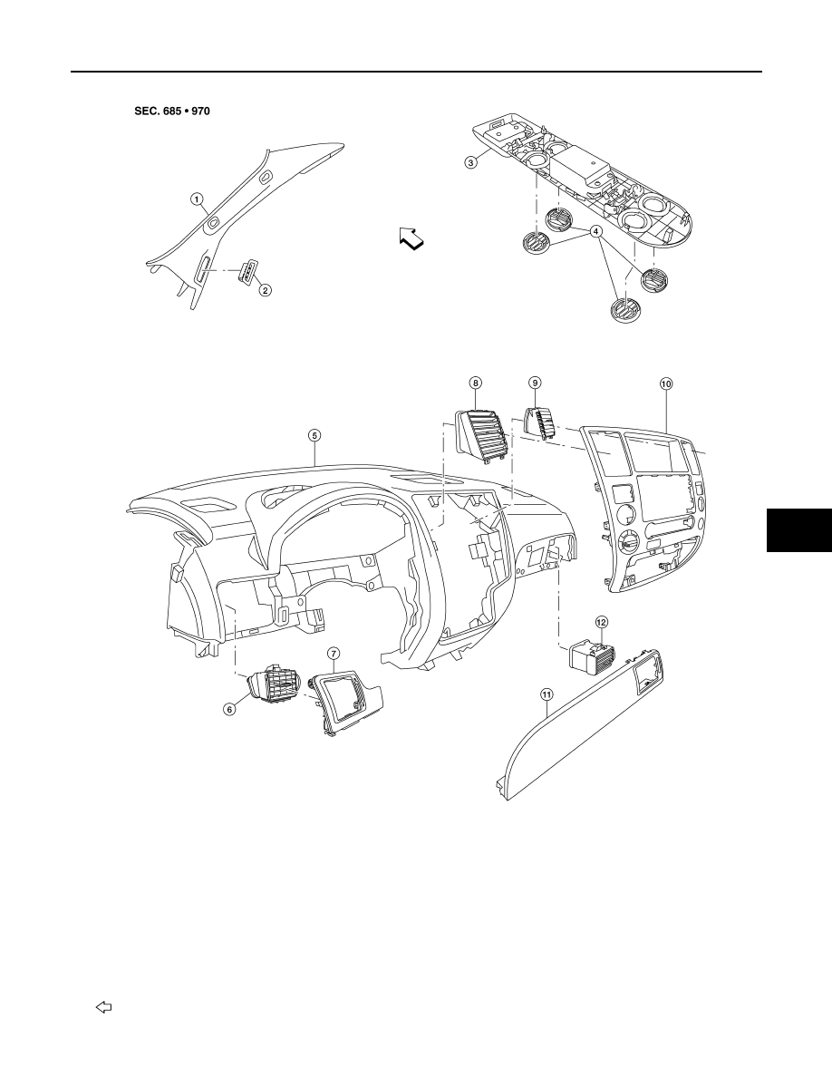
Grilles
ALIIA0067ZZ
1.
Front pillar finisher (RH shown LH
similar)
2.
Side demister grille (RH shown LH
similar)
3.
Rear roof console
4.
Rear roof console grilles
5.
Instrument panel
6.
Side ventilator grille (LH)
7.
Instrument side finisher (LH)
8.
Ventilator grille (LH)
9.
Ventilator grille (RH)
10. Cluster lid C
11. Instrument side finisher (RH)
12. Side ventilator grille (RH)
Front

VTL-36
< ON-VEHICLE REPAIR >
DUCTS AND GRILLES
Removal and Installation
INFOID:0000000005147625
CENTER CONSOLE HEAT DUCT AND REAR FINISHER ASSEMBLY GRILLE
Removal
The center console must be removed and disassembled to remove the heat duct and rear finisher assembly
grille. Refer to
IP-20, "Removal and Installation"
.
Installation
Installation is in the reverse order of removal.
DEFROSTER NOZZLE
Removal
1. Remove the instrument panel trim. Refer to
IP-12, "Removal and Installation"
.
2. Remove the front heater and cooling unit assembly. Refer to
VTL-17, "Removal and Installation"
.
3. Remove the defroster nozzle.
Installation
Installation is in the reverse order of removal.
RH AND LH SIDE DEMISTER DUCT
Removal
1. Remove the instrument panel trim. Refer to
IP-12, "Removal and Installation"
.
2. Remove the RH or LH side demister duct screws.
3. Remove the RH or LH side demister duct.
Installation
Installation is in the reverse order of removal.
RH AND LH VENTILATOR DUCT
Removal
1. Remove the instrument panel trim. Refer to
IP-12, "Removal and Installation"
.
2. Remove the front heater and cooling unit assembly. Refer to
VTL-17, "Removal and Installation"
.
3. Remove the RH or LH ventilator duct.
Installation
Installation is in the reverse order of removal.
CENTER VENTILATOR DUCT
Removal
1. Remove the instrument panel trim. Refer to
IP-12, "Removal and Installation"
.
2. Remove the front heater and cooling unit assembly. Refer to
VTL-17, "Removal and Installation"
.
3. Remove the defroster nozzle.
4. Remove the RH and LH side demister ducts.
5. Remove the RH and LH ventilator ducts.
6. Remove the center ventilator duct.
Installation
Installation is in the reverse order of removal.
FLOOR DUCT
Removal
1. Remove the floor carpet. Refer to
INT-16, "Removal and Installation"
.
2. Remove the two clips and remove the floor duct.
Installation
Installation is in the reverse order of removal.
DUCTS AND GRILLES
VTL-37
< ON-VEHICLE REPAIR >
C
D
E
F
G
H
J
K
L
M
A
B
VTL
N
O
P
REAR OVERHEAD DUCTS
Removal
1. Remove the luggage side finisher lower RH. Refer to
INT-19, "Removal and Installation"
.
2. Remove the headliner. Refer to
INT-17, "Removal and Installation"
.
NOTE:
The rear headliner duct connected to the rear overhead duct is part of the headlining trim panel and is
replaced as an assembly.
3. Remove the two bolts and remove the rear upper and lower overhead ducts.
Installation
Installation is in the reverse order of removal.
REAR FLOOR DUCT
Removal
1. Remove the luggage side finisher lower RH. Refer to
INT-19, "Removal and Installation"
.
2. Reposition the floor carpet out of the way.
3. Remove the two bolts and remove the rear floor duct.
Installation
Installation is in the reverse order of removal.
GRILLES
Removal
1. Remove the interior trim panels as necessary. Refer to
IP-12, "Removal and Installation"
2. Remove the grille from the interior trim panel.
NOTE:
To remove the rear roof console grilles, turn the grille counter-clockwise to release the grille from the rear
roof console.
Installation
Installation is in the reverse order of removal.
WCS
WCS-1
DRIVER INFORMATION & MULTIMEDIA
C
D
E
F
G
H
I
J
K
L
M
B
SECTION
WCS
A
O
P
CONTENTS
WARNING CHIME SYSTEM
BASIC INSPECTION . . . . . . . . .
DIAGNOSIS AND REPAIR WORKFLOW . . ..
Work Flow . . . . . . . . . . . . . . . .....
FUNCTION DIAGNOSIS . . . . . . . ...
WARNING CHIME SYSTEM . . . . . . . ...
WARNING CHIME SYSTEM . . . . . . . . . ...
WARNING CHIME SYSTEM : System Diagram . ...
WARNING CHIME SYSTEM : System Description
. ..
WARNING CHIME SYSTEM : Component Parts
Location . . . . . . . . . . . . . . . . .....
WARNING CHIME SYSTEM : Component De-
scription . . . . . . . . . . . . . . . . .....
LIGHT REMINDER WARNING CHIME . . . . . ...
LIGHT REMINDER WARNING CHIME : System
Diagram . . . . . . . . . . . . . . . . .....
LIGHT REMINDER WARNING CHIME : System
Description . . . . . . . . . . . . . . . ....
LIGHT REMINDER WARNING CHIME : Compo-
nent Parts Location . . . . . . . . . . . . ...
LIGHT REMINDER WARNING CHIME : Compo-
nent Description . . . . . . . . . . . . . ....
SEAT BELT WARNING CHIME . . . . . . . . ..
SEAT BELT WARNING CHIME : System Diagram
. ..
SEAT BELT WARNING CHIME : System Descrip-
tion . . . . . . . . . . . . . . . . . . ....
SEAT BELT WARNING CHIME : Component
Parts Location . . . . . . . . . . . . . . ...
SEAT BELT WARNING CHIME : Component De-
scription . . . . . . . . . . . . . . . . .....
KEY WARNING CHIME . . . . . . . . . . . .
KEY WARNING CHIME : System Diagram . . .
KEY WARNING CHIME : System Description . .
KEY WARNING CHIME : Component Parts Loca-
tion . . . . . . . . . . . . . . . . . . ...
KEY WARNING CHIME : Component Description .
DIAGNOSIS SYSTEM (METER) . . . . . ...
CONSULT-III Function (METER/M&A) . . . . .
DIAGNOSIS SYSTEM (BCM) . . . . . . ...
BUZZER . . . . . . . . . . . . . . . . . .
BUZZER : CONSULT-III Function (BCM - BUZZ-
ER) . . . . . . . . . . . . . . . . . . ..
COMPONENT DIAGNOSIS . . . . . . .
POWER SUPPLY AND GROUND CIRCUIT .
COMBINATION METER . . . . . . . . . . .
COMBINATION METER : Diagnosis Procedure . .
BCM (BODY CONTROL MODULE) . . . . . . ..
BCM (BODY CONTROL MODULE) : Diagnosis
Procedure . . . . . . . . . . . . . . . .
METER BUZZER CIRCUIT . . . . . . . ...
Description . . . . . . . . . . . . . . . ...
Component Function Check . . . . . . . . .
Diagnosis Procedure . . . . . . . . . . . ..
SEAT BELT BUCKLE SWITCH SIGNAL CIR-
CUIT . . . . . . . . . . . . . . . . ..
Description . . . . . . . . . . . . . . . ...
Component Function Check . . . . . . . . ..
Diagnosis Procedure . . . . . . . . . . . ..
Component Inspection . . . . . . . . . . . .
KEY SWITCH SIGNAL CIRCUIT . . . . . ..
Description . . . . . . . . . . . . . . . ...
Component Function Check . . . . . . . . ..
Diagnosis Procedure . . . . . . . . . . . ..
Component Inspection . . . . . . . . . . . .
Нет комментариевНе стесняйтесь поделиться с нами вашим ценным мнением.
Текст