Infiniti QX56 (JA60). Manual — part 786
SUNROOF SWITCH CIRCUIT
RF-13
< COMPONENT DIAGNOSIS >
C
D
E
F
G
H
I
J
L
M
A
B
RF
N
O
P
4. Check continuity between sunroof switch connector R104 (A) and ground.
Are the continuity test results as specified?
YES
>> GO TO 3
NO
>> Repair harness or connector.
3.
CHECK SUNROOF SWITCH
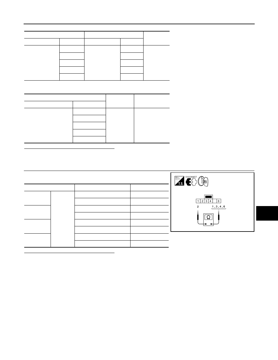
1. Check continuity between sunroof switch terminals.
Are the continuity test results as specified?
YES
>> Sunroof switch is operating normally.
NO
>> Replace sunroof switch (map lamp assembly).
A
B
Continuity
Connector
Terminal
Connector
Terminal
R104
1
R4
3
Yes
2
8
3
9
4
4
6
10
A
—
Continuity
Connector
Terminal
R104
1
Ground
No
2
3
4
6
Terminals
Sunroof switch position
Continuity
1
2
SLIDE CLOSE
Yes
Other than above
No
3
SLIDE OPEN
Yes
Other than above
No
4
TILT UP
Yes
Other than above
No
6
TILT DOWN
Yes
Other than above
No
ALKIA0874ZZ
RF-14
< COMPONENT DIAGNOSIS >
DOOR SWITCH
DOOR SWITCH
Description
INFOID:0000000005147283
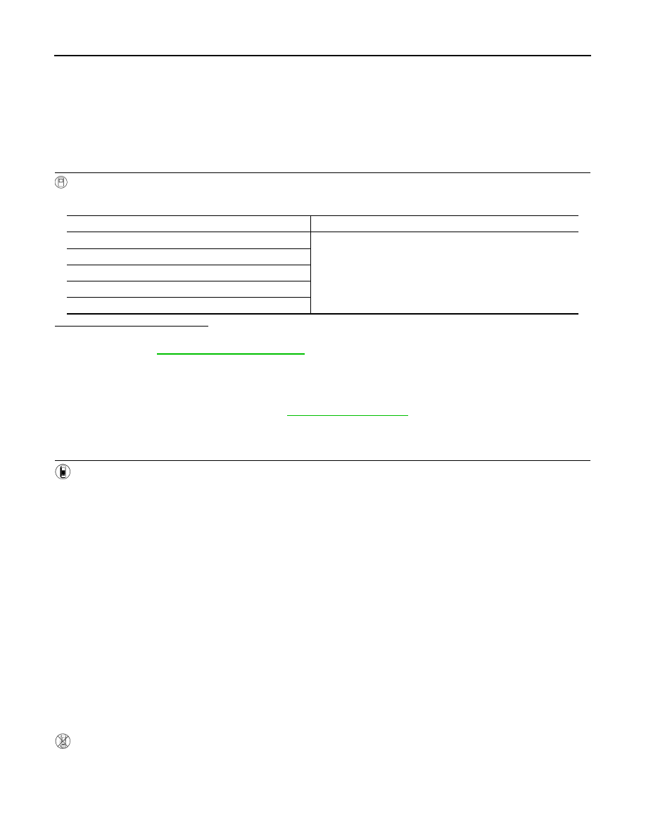
Detects door open/close condition.
Component Function Check
INFOID:0000000005147284
1.
CHECK FUNCTION
With CONSULT-III
Check door switches in data monitor mode with CONSULT-III.
Is the inspection result normal?
YES
>> Door switch is OK.
NO
>> Refer to
Diagnosis Procedure
INFOID:0000000005147285
Regarding Wiring Diagram information, refer to
1.
CHECK DOOR SWITCHES INPUT SIGNAL
With CONSULT-III
Check door switches ("DOOR SW-DR", "DOOR SW-AS", "DOOR SW-RL", "DOOR SW-RR", "BACK DOOR
SW") in DATA MONITOR mode with CONSULT–III.
• When doors are open:
• When doors are closed:
Without CONSULT-III
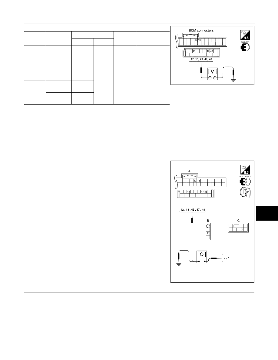
Check voltage between BCM connector M18 or M19 terminals 12, 13, 43, 47, 48 and ground.
Monitor item
Condition
DOOR SW-DR
CLOSE
→ OPEN: OFF → ON
DOOR SW-AS
DOOR SW-RL
DOOR SW-RR
BACK DOOR SW
DOOR SW-DR
:ON
DOOR SW-AS
:ON
DOOR SW-RL
:ON
DOOR SW-RR
:ON
BACK DOOR SW
:ON
DOOR SW-DR
:OFF
DOOR SW-AS
:OFF
DOOR SW-RL
:OFF
DOOR SW-RR
:OFF
BACK DOOR SW
:OFF
DOOR SWITCH
RF-15
< COMPONENT DIAGNOSIS >
C
D
E
F
G
H
I
J
L
M
A
B
RF
N
O
P
Is the inspection result normal?
YES
>> Door switch circuit is OK.
NO
>> GO TO 2
2.
CHECK DOOR SWITCH CIRCUIT
1. Turn ignition switch OFF.
2. Disconnect door switch and BCM.
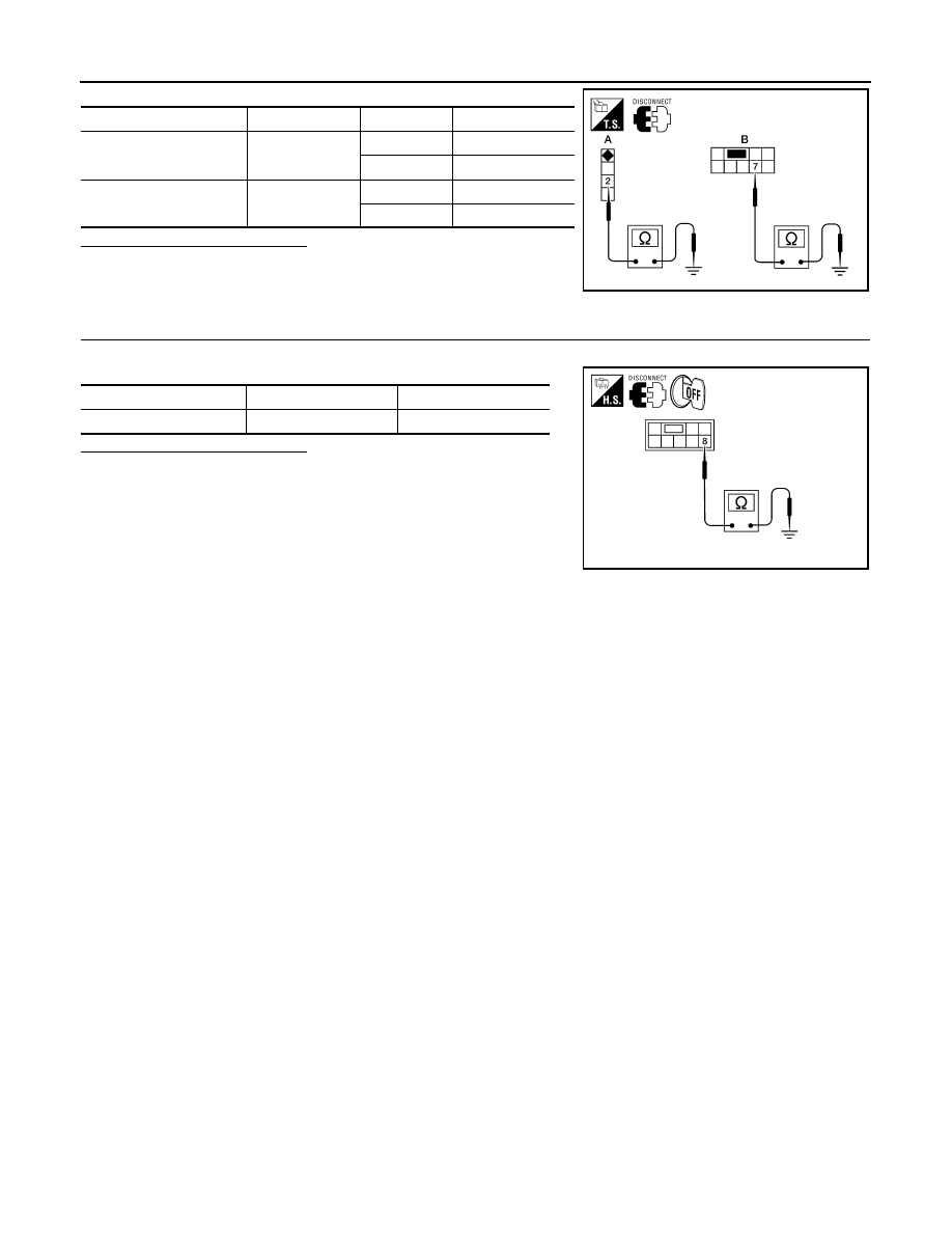
3. Check continuity between BCM connector (A) M18, M19 terminals 12, 13, 43, 47, 48 and door switch con-
nector (B) B8 (Front LH), B108 (Front RH), B18 (Rear LH), B116 (Rear RH) terminal 2 or back door latch
connector (C) D503 terminal 7.
4. Check continuity between door switch connector (B) B8 (Front
LH), B108 (Front RH), B18 (Rear LH), B116 (Rear RH) terminal
2 or back door latch connector (C) D503 terminal 7 and ground.
Is the inspection result normal?
YES
>> GO TO 3
NO
>> Repair or replace harness.
3.
CHECK DOOR SWITCHES
• Disconnect door switch harness.
• Check continuity between door switch connector terminals.
Connec-
tor
Item
Terminals
Condition
Voltage (V)
(Approx.)
( + )
( – )
M19
Back door
switch/latch
43
Ground
Open
↓
Closed
0
↓
Battery voltage
Front door
switch LH
47
Rear door
switch LH
48
M18
Front door
switch RH
12
Rear door
switch RH
13
LIIA1041E
2 - 47
:Continuity should exist
2 - 12
:Continuity should exist
2 - 48
:Continuity should exist
2 - 13
:Continuity should exist
7 - 43
:Continuity should exist
2 - Ground
:Continuity should not exist
7 - Ground
:Continuity should not exist
ALKIA0689ZZ
RF-16
< COMPONENT DIAGNOSIS >
DOOR SWITCH
Is the inspection result normal?
YES
>> Door switch circuit is OK.
NO
>> (Front and rear doors) Replace door switch.
NO
>> (Back door) GO TO 4
4.
CHECK BACK DOOR SWITCH CIRCUIT
• Check continuity between door switch connector terminal and ground.
Is the inspection result normal?
YES
>> Replace back door switch.
NO
>> Repair or replace harness.
Switch
Terminals
Condition
Continuity
A: Door switch
(front and rear)
2 – Ground
Open
Yes
Closed
No
B: Back door switch
7 – Ground
Open
Yes
Closed
No
ALKIA0690ZZ
Connector
Terminals
Continuity
Back door switch
8 – Ground
Yes
ALKIA0691ZZ
Нет комментариевНе стесняйтесь поделиться с нами вашим ценным мнением.
Текст