Infiniti QX56 (JA60). Manual — part 784
INSPECTION AND ADJUSTMENT
RF-5
< BASIC INSPECTION >
C
D
E
F
G
H
I
J
L
M
A
B
RF
N
O
P
INSPECTION AND ADJUSTMENT
ADDITIONAL SERVICE WHEN REPLACING CONTROL UNIT
ADDITIONAL SERVICE WHEN REPLACING CONTROL UNIT : Description
INFOID:0000000005147269
MEMORY RESET PROCEDURE
1. Please observe the following instructions at confirming the sunroof operation.
NOTE:
Do not disconnect the electronic power while the sunroof is operating or within 5 seconds after the sunroof
stops. (to wipe-out the memory of lid position and operating friction.)
2. Initialization of system should be conducted after the following conditions.
• When the sunroof motor is changed.
• When the sunroof does not operate normally. (Incomplete initialization conditions)
ADDITIONAL SERVICE WHEN REPLACING CONTROL UNIT : Special Repair Re-
quirement
INFOID:0000000005147270
INITIALIZATION PROCEDURE
If the sunroof does not close or open automatically, use the following procedure to return sunroof operation to
normal.
1. Turn ignition switch ON.
2. Push and hold the sunroof tilt switch in the forward (DOWN) position until the sunroof is fully closed.
3. After the sunroof has closed all the way, push and hold the tilt switch forward (DOWN) again for more than
2 seconds to re-learn motor position.
4. Initialization is complete if the sunroof operates normally.
BASIC INSPECTION
BASIC INSPECTION : Special Repair Requirement
INFOID:0000000005147271
BASIC INSPECTION
1.
INSPECTION START
1. Check the service history.
2. Check the following parts.
• Fuse/circuit breaker blown.
• Poor connection, open or short circuit of harness connector.
• Battery voltage.
Is the inspection result normal?
YES
>> Inspection End.
NO
>> Repair or replace the malfunctioning parts.
RF-6
< FUNCTION DIAGNOSIS >
SUNROOF SYSTEM
FUNCTION DIAGNOSIS
SUNROOF SYSTEM
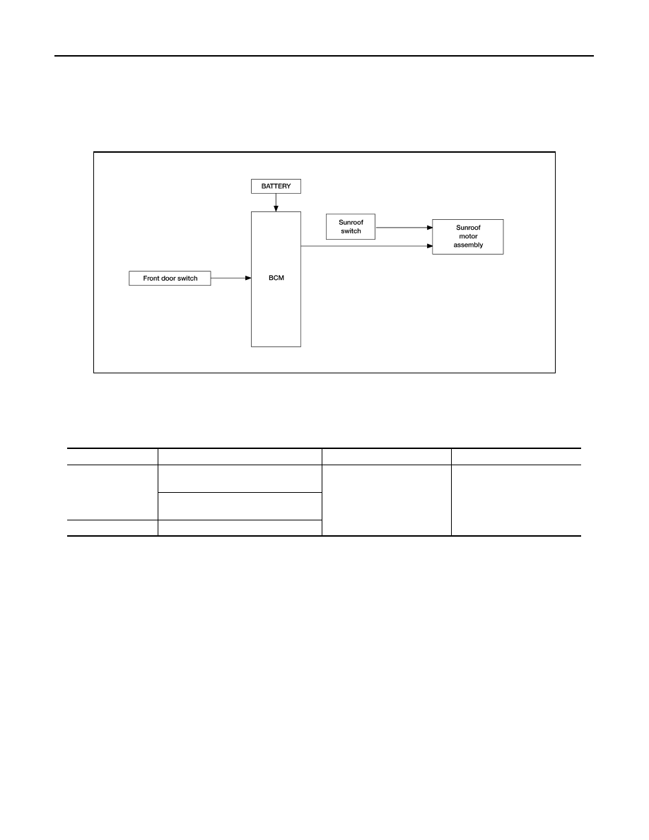
System Diagram
INFOID:0000000005147272
SUNROOF
System Description
INFOID:0000000005147273
SUNROOF SYSTEM
INPUT/OUTPUT SIGNAL CHART
SUNROOF OPERATION
• The sunroof motor assembly operates with a power supply that is output from the BCM while the ignition
switch is ON or retained power is operating.
• The tilt up/down & slide open/close signals from the sunroof switch enable the sunroof motor to move arbi-
trarily.
AUTO OPERATION
The sunroof AUTO feature makes it possible to slide open and slide close or tilt up and tilt down the sunroof
without holding the sunroof switch in the slide open/tilt down or slide close/tilt up position.
RETAINED POWER OPERATION
Retained power operation is an additional power supply function that enables the sunroof system to operate
up to 45 seconds after the ignition switch is turned OFF.
Retained power function cancel conditions
• When a front door is opened (door switch ON)
• When ignition switch is turned ON again.
• When 45 seconds elapse on the timer.
ALKIA0861GB
Item
Input signal to sunroof motor assembly
Sunroof motor function
Actuator
Sunroof switch
Sunroof switch signal (tilt down or slide
open)
Sunroof control
Sunroof motor
Sunroof switch signal (tilt up or slide
close)
BCM
RAP signal
SUNROOF SYSTEM
RF-7
< FUNCTION DIAGNOSIS >
C
D
E
F
G
H
I
J
L
M
A
B
RF
N
O
P
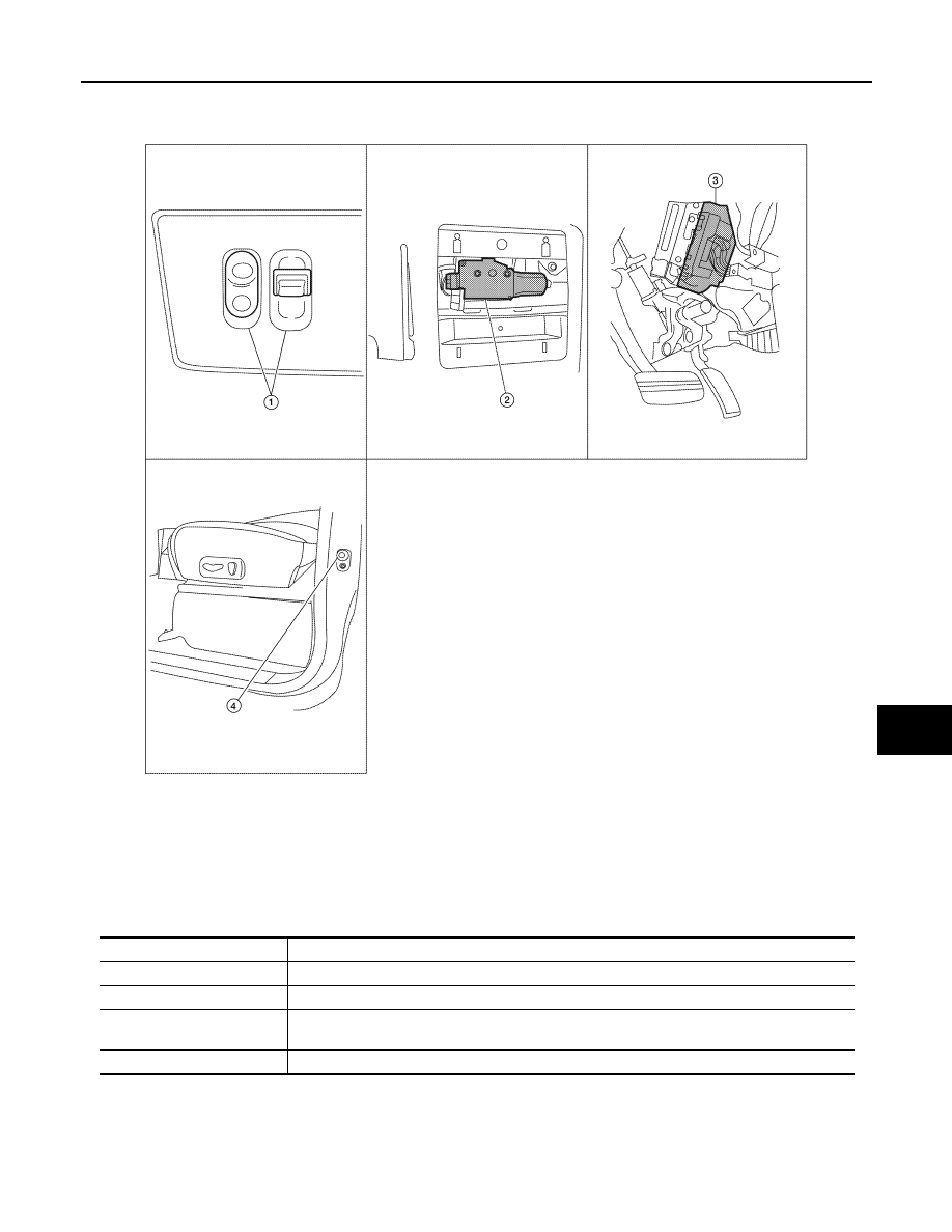
Component Parts Location
INFOID:0000000005147274
Component Description
INFOID:0000000005147275
ALKIA0867ZZ
1.
Sunroof switch R104
2.
Sunroof motor assembly R4
3.
BCM M18, M19, M20
(View with instrument panel re-
moved)
4.
Front door switch LH B8, RH B108
Component
Function
BCM
Supplies power to the sunroof motor assembly.
Sunroof switch
Transmits tilt up/down & slide open/close operation signal to sunroof motor assembly.
Sunroof motor assembly
The sunroof motor and integrated CPU enables tilt up/down & slide open/close as requested by
the sunroof switch.
Front door switch
Detects door open/close condition and transmits to BCM.

RF-8
< FUNCTION DIAGNOSIS >
DIAGNOSIS SYSTEM (BCM)
DIAGNOSIS SYSTEM (BCM)
COMMON ITEM
COMMON ITEM : CONSULT-III Function (BCM - COMMON ITEM)
INFOID:0000000005370295
APPLICATION ITEM
CONSULT-III performs the following functions via CAN communication with BCM.
SYSTEM APPLICATION
BCM can perform the following functions for each system.
NOTE:
It can perform the diagnosis modes except the following for all sub system selection items.
RETAINED PWR
Diagnosis mode
Function Description
WORK SUPPORT
Changes the setting for each system function.
SELF-DIAG RESULTS
Displays the diagnosis results judged by BCM. Refer to
CAN DIAG SUPPORT MNTR
Monitors the reception status of CAN communication viewed from BCM.
DATA MONITOR
The BCM input/output signals are displayed.
ACTIVE TEST
The signals used to activate each device are forcibly supplied from BCM.
ECU IDENTIFICATION
The BCM part number is displayed.
CONFIGURATION
• Enables to read and save the vehicle specification.
• Enables to write the vehicle specification when replacing BCM.
System
Sub system selection item
Diagnosis mode
WORK SUPPORT
DATA MONITOR
ACTIVE TEST
BCM
BCM
×
Door lock
DOOR LOCK
×
×
×
Rear window defogger
REAR DEFOGGER
×
Warning chime
BUZZER
×
×
Interior room lamp timer
INT LAMP
×
×
×
Remote keyless entry system
MULTI REMOTE ENT
×
×
Exterior lamp
HEAD LAMP
×
×
×
Wiper and washer
WIPER
×
×
×
Turn signal and hazard warning lamps FLASHER
×
×
Air conditioner
AIR CONDITONER
×
Intelligent Key system
INTELLIGENT KEY
×
Combination switch
COMB SW
×
Immobilizer
IMMU
×
×
Interior room lamp battery saver
BATTERY SAVER
×
×
×
Back door open
TRUNK
×
×
RAP (retained accessory power)
RETAINED PWR
×
×
×
Signal buffer system
SIGNAL BUFFER
×
×
TPMS (tire pressure monitoring sys-
tem)
AIR PRESSURE MONITOR
×
×
×
Vehicle security system
THEFT ALM
×
×
×
Panic alarm system
PANIC ALARM
×
Нет комментариевНе стесняйтесь поделиться с нами вашим ценным мнением.
Текст