Infiniti QX56 (JA60). Manual — part 472
EM-42
< ON-VEHICLE REPAIR >
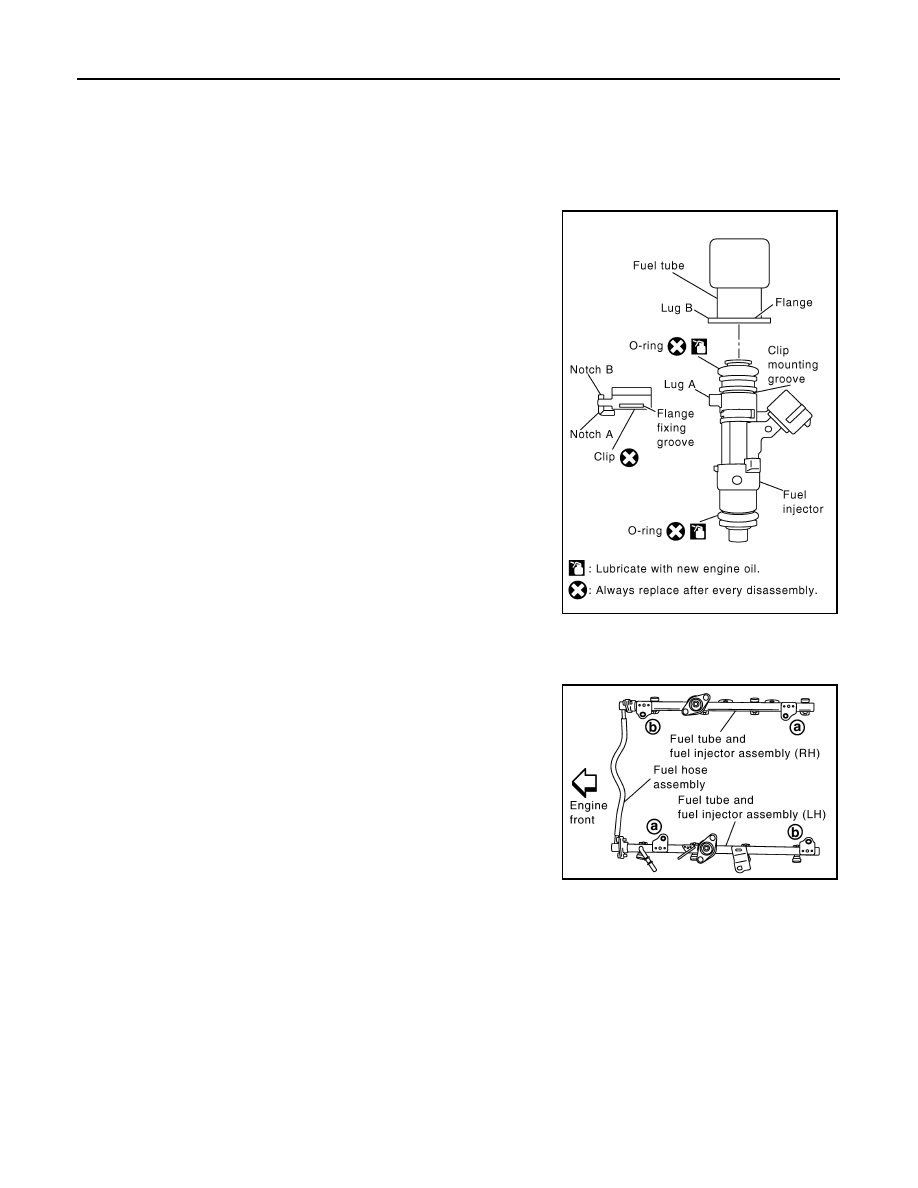
FUEL INJECTOR AND FUEL TUBE
• Lubricate O-ring with new engine oil.
• Do not clean O-ring with solvent.
• Make sure that O-ring and its mating part are free of foreign material.
• When installing O-ring, be careful not to scratch it with tool or fingernails. Also be careful not to
twist or stretch O-ring. If O-ring was stretched while it was being attached, do not insert it
quickly into fuel tube.
• Insert O-ring straight into fuel tube. Do not angle or twist it.
3. Install fuel injector to fuel tube.
a. Insert clip into clip mounting groove on fuel injector.
• Insert clip so that lug “A” of fuel injector matches notch “A” of
the clip.
CAUTION:
• Do not reuse clip. Replace it with a new one.
• Be careful to keep clip from interfering with O-ring. If
interference occurs, replace O-ring.
b. Insert fuel injector into fuel tube with clip attached.
• Insert it while matching it to the axial center.
• Insert fuel injector so that lug “B” of fuel tube matches notch
“B” of the clip.
• Make sure that fuel tube flange is securely fixed in flange fixing
groove on clip.
c.
Make sure that installation is complete by checking that fuel
injector does not rotate or come off.
• Make sure that protrusions of fuel injectors are aligned with
cutouts of clips after installation.
4. Install fuel tube and fuel injector assembly to intake manifold.
CAUTION:
Be careful not to let tip of injector nozzle come in contact with other parts.
• Tighten fuel tube assembly bolts “a” to “b” in illustration and in
two steps.
5. Install fuel hose assembly.
• Follow the precautions for fuel injector when handling O-ring.
• Insert connectors straight, making sure that the axis is lined up with fuel tube side to prevent O-ring from
being damaged.
• Tighten bolts evenly in several steps.
• Make sure that there is no gap between flange and fuel tube after tightening bolts.
6. Installation of the remaining components is in the reverse order of removal.
INSPECTION AFTER INSTALLATION
After installing fuel tubes, make sure there are no fuel leaks at connections using the following steps.
1. Apply fuel pressure to fuel lines by turning ignition switch ON (with engine stopped). Then check for fuel
leaks at connections.
2. Start the engine and rev it up and check for fuel leaks at connections.
WARNING:
KBIA2507E
1st step
: 12.8 N·m (1.3 kg-m, 9 ft-lb)
2nd step
: 24.5 N·m (2.5 kg-m, 18 ft-lb)
KBIA2474E
FUEL INJECTOR AND FUEL TUBE
EM-43
< ON-VEHICLE REPAIR >
C
D
E
F
G
H
I
J
K
L
M
A
EM
N
P
O
Do not touch the engine immediately after stopping, as engine becomes extremely hot.
NOTE:
Use mirrors for checking on hidden points.
EM-44
< ON-VEHICLE REPAIR >
TIMING CHAIN
TIMING CHAIN
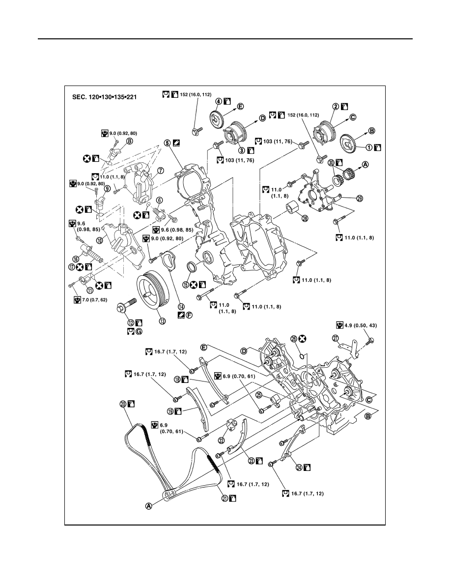
Exploded View
INFOID:0000000005148999
AWBIA0818GB
TIMING CHAIN
EM-45
< ON-VEHICLE REPAIR >
C
D
E
F
G
H
I
J
K
L
M
A
EM
N
P
O
Removal and Installation
INFOID:0000000005149000
NOTE:
• To remove timing chain and associated parts, start with those on the LH bank. The procedure for removing
parts on the RH bank is omitted because it is the same as that for removal on the LH bank.
• To install timing chain and associated parts, start with those on the RH bank. The procedure for installing
parts on the LH bank is omitted because it is the same as that for installation on the RH bank.
REMOVAL
1. Remove the engine assembly from the vehicle. Refer to
EM-78, "Removal and Installation"
2. Remove the following components and related parts:
• Drive belt auto tensioner and idler pulley. Refer to
EM-13, "Removal and Installation"
.
• Thermostat housing and water hose. Refer to
CO-22, "Removal and Installation"
• Power steering oil pump bracket. Refer to
ST-26, "Removal and Installation"
.
• Oil pan (lower), (upper) and oil strainer. Refer to
EM-33, "Removal and Installation"
.
• Rocker cover. Refer to
EM-38, "Removal and Installation"
.
• Generator and generator bracket. Refer to
CHG-21, "Removal and Installation"
.
• Water pump. Refer to
.
3. Disconnect and remove the camshaft position sensor.
4. Disconnect and remove the intake valve timing control position sensor (RH and LH).
5. Disconnect and remove the intake valve timing control solenoid valve (RH and LH).
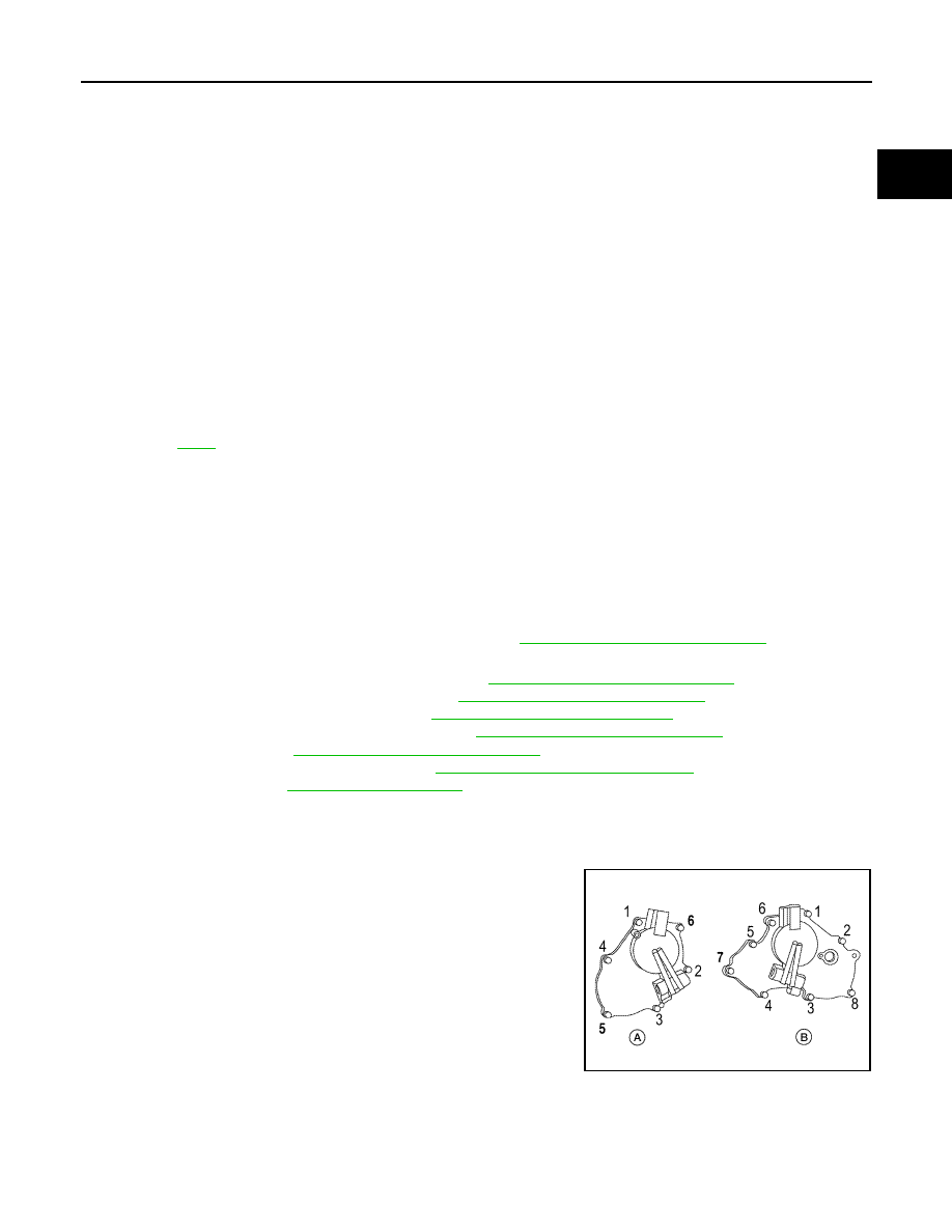
6. Remove the Intake valve timing control solenoid valve cover
(RH) (A) and Intake valve timing control solenoid valve cover
(LH) (B) as follows:
a. Loosen and remove the bolts in reverse order as shown.
b. Cut the liquid gasket and remove the covers using Tool.
CAUTION:
Do not damage mating surfaces.
1.
Camshaft sprocket LH bank EXH
2.
Camshaft sprocket LH bank INT
(VTC)
3.
Camshaft sprocket RH bank INT
(VTC)
4.
Camshaft sprocket RH bank EXH
5.
Front cover
6.
Intake valve timing control solenoid
valve (RH)
7.
Intake valve timing control solenoid
valve cover (RH)
8.
Intake valve timing control position
sensor (RH)
9.
Intake valve timing control position
sensor (LH)
10. Intake valve timing control solenoid
valve cover (LH)
11.
Camshaft position sensor (PHASE)
12
Crankshaft pulley bolt
13. Crankshaft pulley
14.
Chain tensioner cover
15.
Front oil seal
16. Intake valve timing control solenoid
valve (RH)
17.
O-ring
18.
Timing chain tension guide RH bank
19. Timing chain slack guide (RH)
20.
Timing chain RH bank
21.
Timing chain LH bank
22. Chain tensioner (RH)
23.
Timing chain slack guide LH bank
24.
Timing chain tension guide LH bank
25. Chain tensioner (LH)
26.
O-ring
27.
Bracket
28. Oil pump drive spacer
29.
Oil pump assembly
30.
Crankshaft sprockets
A.
To crankshaft
B.
To camshaft LH bank EXH
C.
To camshaft LH bank INT (VTC)
D.
To camshaft RH bank INT (VTC)
E.
To camshaft RH bank EXH
F.
Apply sealant to mating side
G.
Tool number
: KV10111100 (J-37228)
AWBIA0815ZZ
Нет комментариевНе стесняйтесь поделиться с нами вашим ценным мнением.
Текст