Infiniti QX56 (JA60). Manual — part 670
LAN
DLC BRANCH LINE CIRCUIT
LAN-79
< COMPONENT DIAGNOSIS >
[CAN]
C
D
E
F
G
H
I
J
K
L
B
A
O
P
N
DLC BRANCH LINE CIRCUIT
Diagnosis Procedure
INFOID:0000000005146486
1.
CHECK CONNECTOR
1. Turn the ignition switch OFF.
2. Disconnect the battery cable from the negative terminal.
3. Check the terminals and connectors of the data link connector for damage, bend and loose connection
(connector side and harness side).
Is the inspection result normal?
YES
>> GO TO 2.
NO
>> Repair the terminal and connector.
2.
CHECK HARNESS FOR OPEN CIRCUIT
Check the resistance between the data link connector terminals.
Is the measurement value within the specification?
YES (Present error)>>Check the following items again.
• Decision of CAN system type.
• Not received CONSULT-III data [SELF-DIAG RESULTS, CAN DIAG SUPPORT MNTR (“ECU
list” included)].
• Procedure for detecting root cause.
YES (Past error)>>Error was detected in the data link connector branch line circuit.
NO
>> Repair the data link connector branch line.
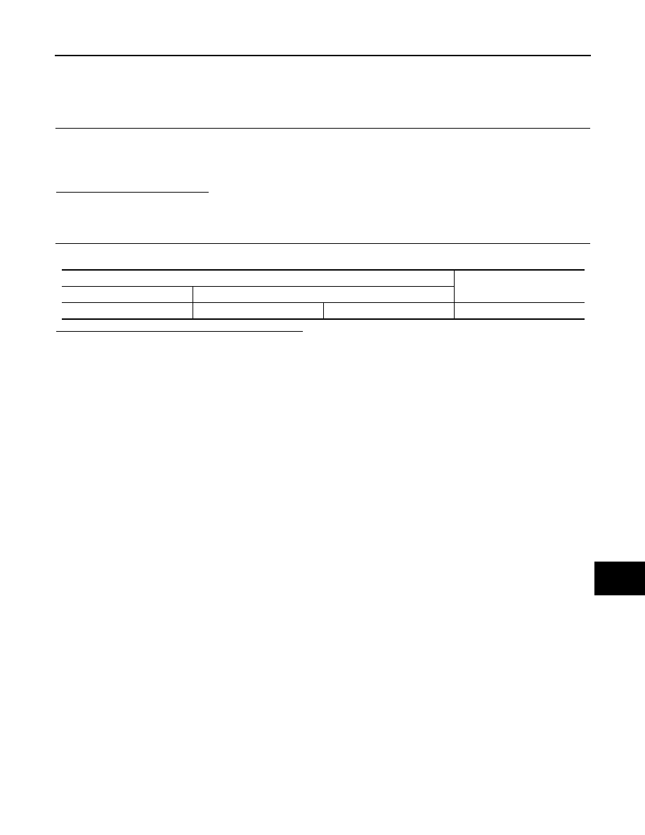
Data link connector
Resistance (
Ω)
Connector No.
Terminal No.
M22
6
14
Approx. 54 – 66

LAN-80
< COMPONENT DIAGNOSIS >
[CAN]
HVAC BRANCH LINE CIRCUIT
HVAC BRANCH LINE CIRCUIT
Diagnosis Procedure
INFOID:0000000005146487
1.
CHECK CONNECTOR
1. Turn the ignition switch OFF.
2. Disconnect the battery cable from the negative terminal.
3. Check the terminals and connectors of the A/C auto amp. for damage, bend and loose connection (unit
side and connector side).
Is the inspection result normal?
YES
>> GO TO 2.
NO
>> Repair the terminal and connector.
2.
CHECK HARNESS FOR OPEN CIRCUIT
1. Disconnect the connector of A/C auto amp.
2. Check the resistance between the A/C auto amp. harness connector terminals.
Is the measurement value within the specification?
YES
>> GO TO 3.
NO
>> Repair the A/C auto amp. branch line.
3.
CHECK POWER SUPPLY AND GROUND CIRCUIT
Check the power supply and the ground circuit of the A/C auto amp. Refer to
and Ground Diagnosis Procedure"
Is the inspection result normal?
YES (Present error)>>Replace the A/C auto amp. Refer to
VTL-7, "Removal and Installation"
.
YES (Past error)>>Error was detected in the A/C auto amp. branch line.
NO
>> Repair the power supply and the ground circuit.
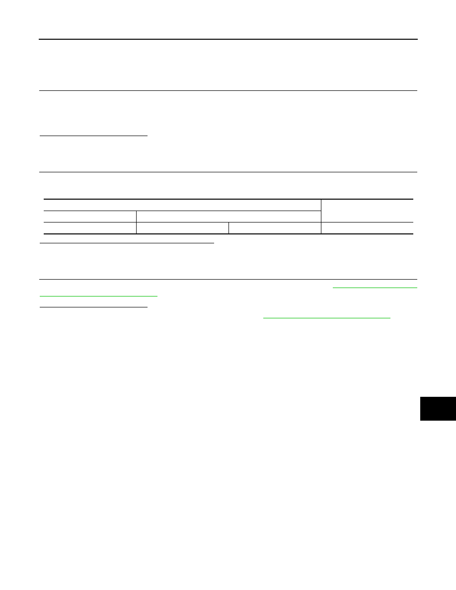
A/C auto amp. harness connector
Resistance (
Ω)
Connector No.
Terminal No.
M50
41
40
Approx. 54 – 66
LAN
I-KEY BRANCH LINE CIRCUIT
LAN-81
< COMPONENT DIAGNOSIS >
[CAN]
C
D
E
F
G
H
I
J
K
L
B
A
O
P
N
I-KEY BRANCH LINE CIRCUIT
Diagnosis Procedure
INFOID:0000000005146488
1.
CHECK CONNECTOR
1. Turn the ignition switch OFF.
2. Disconnect the battery cable from the negative terminal.
3. Check the terminals and connectors of the Intelligent Key unit for damage, bend and loose connection
(unit side and connector side).
Is the inspection result normal?
YES
>> GO TO 2.
NO
>> Repair the terminal and connector.
2.
CHECK HARNESS FOR OPEN CIRCUIT
1. Disconnect the connector of Intelligent Key unit.
2. Check the resistance between the Intelligent Key unit harness connector terminals.
Is the measurement value within the specification?
YES
>> GO TO 3.
NO
>> Repair the Intelligent Key unit branch line.
3.
CHECK POWER SUPPLY AND GROUND CIRCUIT
Check the power supply and the ground circuit of the Intelligent Key unit. Refer to
KEY UNIT : Diagnosis Procedure"
Is the inspection result normal?
YES (Present error)>>Replace the Intelligent Key unit. Refer to
SEC-120, "Removal and Installation"
YES (Past error)>>Error was detected in the Intelligent Key unit branch line.
NO
>> Repair the power supply and the ground circuit.
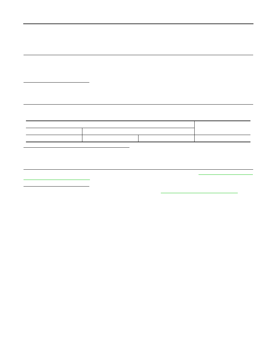
Intelligent Key unit harness connector
Resistance (
Ω)
Connector No.
Terminal No.
M70
2
3
Approx. 54 – 66
LAN-82
< COMPONENT DIAGNOSIS >
[CAN]
M&A BRANCH LINE CIRCUIT
M&A BRANCH LINE CIRCUIT
Diagnosis Procedure
INFOID:0000000005146489
1.
CHECK CONNECTOR
1. Turn the ignition switch OFF.
2. Disconnect the battery cable from the negative terminal.
3. Check the terminals and connectors of the combination meter for damage, bend and loose connection
(unit side and connector side).
Is the inspection result normal?
YES
>> GO TO 2.
NO
>> Repair the terminal and connector.
2.
CHECK HARNESS FOR OPEN CIRCUIT
1. Disconnect the connector of combination meter.
2. Check the resistance between the combination meter harness connector terminals.
Is the measurement value within the specification?
YES
>> GO TO 3.
NO
>> Repair the combination meter branch line.
3.
CHECK POWER SUPPLY AND GROUND CIRCUIT
Check the power supply and the ground circuit of the combination meter. Refer to
Is the inspection result normal?
YES (Present error)>>Replace the combination meter. Refer to
MWI-100, "Removal and Installation"
YES (Past error)>>Error was detected in the combination meter branch line.
NO
>> Repair the power supply and the ground circuit.
Combination meter harness connector
Resistance (
Ω)
Connector No.
Terminal No.
M24
10
11
Approx. 54 – 66
Нет комментариевНе стесняйтесь поделиться с нами вашим ценным мнением.
Текст