Infiniti QX56 (JA60). Manual — part 668
LAN
MAIN LINE BETWEEN 4WD AND ABS CIRCUIT
LAN-71
< COMPONENT DIAGNOSIS >
[CAN]
C
D
E
F
G
H
I
J
K
L
B
A
O
P
N
MAIN LINE BETWEEN 4WD AND ABS CIRCUIT
Diagnosis Procedure
INFOID:0000000005152915
1.
CHECK HARNESS CONTINUITY (OPEN CIRCUIT)
1. Turn the ignition switch OFF.
2. Disconnect the battery cable from the negative terminal.
3. Disconnect the following harness connectors.
-
ECM
-
Transfer control unit
-
ABS actuator and electric unit (control unit)
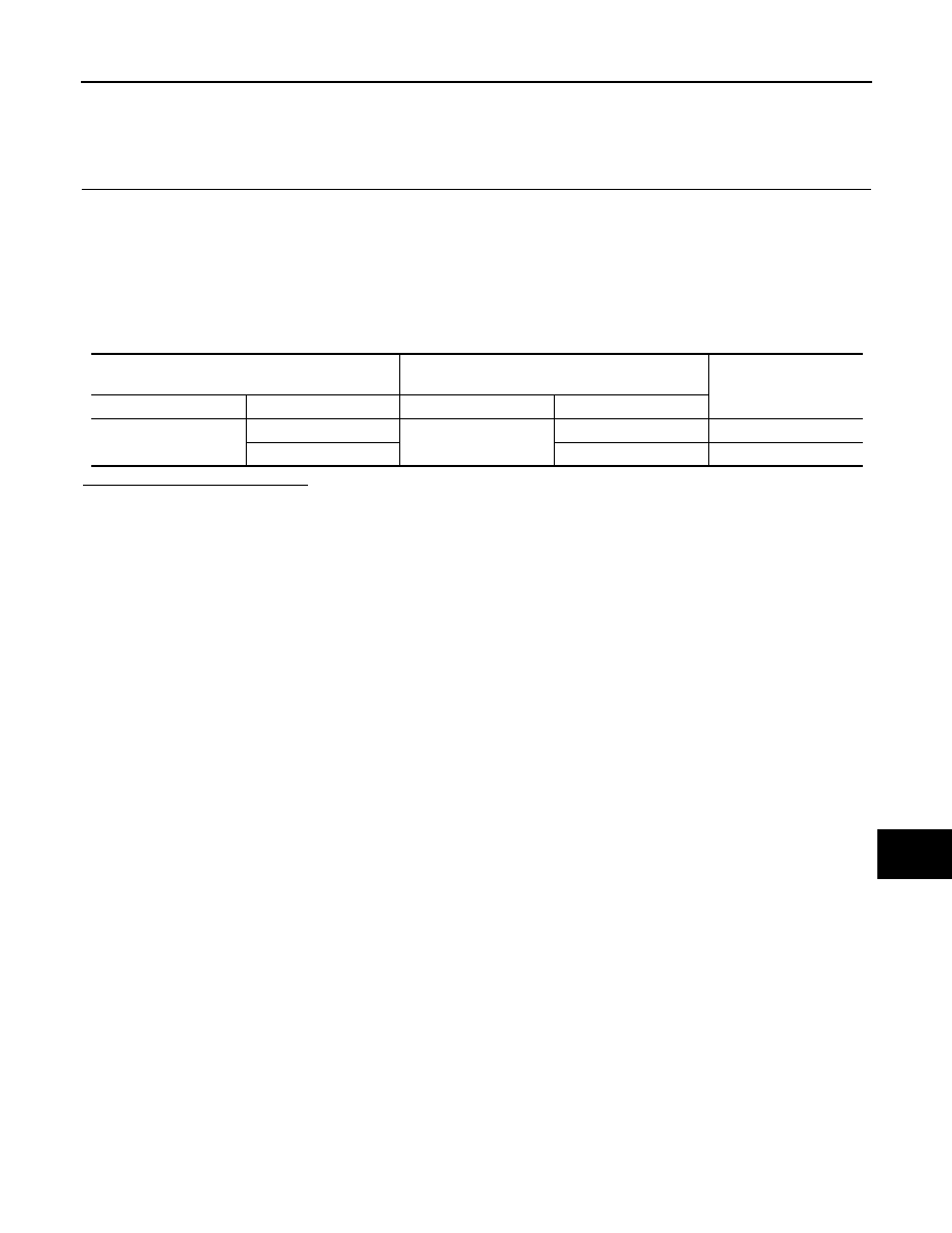
4. Check the continuity between the transfer control unit harness connector and the ABS actuator and elec-
tric unit (control unit) harness connector.
Is the inspection result normal?
YES (Present error)>>Check the following items again.
• Decision of CAN system type.
• Not received CONSULT-III data [SELF-DIAG RESULTS, CAN DIAG SUPPORT MNTR (“ECU
list” included)].
• Procedure for detecting root cause.
YES (Past error)>>Error was detected in the main line between the transfer control unit and the ABS actuator
and electric unit (control unit).
NO
>> Repair the main line between the transfer control unit and the ABS actuator and electric unit (con-
trol unit).
Transfer control unit harness connector
ABS actuator and electric unit (control unit)
harness connector
Continuity
Connector No.
Terminal No.
Connector No.
Terminal No.
E142
7
E125
11
Existed
8
15
Existed

LAN-72
< COMPONENT DIAGNOSIS >
[CAN]
ECM BRANCH LINE CIRCUIT
ECM BRANCH LINE CIRCUIT
Diagnosis Procedure
INFOID:0000000005146479
1.
CHECK CONNECTOR
1. Turn the ignition switch OFF.
2. Disconnect the battery cable from the negative terminal.
3. Check the following terminals and connectors for damage, bend and loose connection (unit side and con-
nector side).
-
ECM
-
Harness connector E5
-
Harness connector F14
Is the inspection result normal?
YES
>> GO TO 2.
NO
>> Repair the terminal and connector.
2.
CHECK HARNESS FOR OPEN CIRCUIT
1. Disconnect the connector of ECM.
2. Check the resistance between the ECM harness connector terminals.
Is the measurement value within the specification?
YES
>> GO TO 3.
NO
>> Repair the ECM branch line.
3.
CHECK POWER SUPPLY AND GROUND CIRCUIT
Check the power supply and the ground circuit of the ECM. Refer to
.
Is the inspection result normal?
YES (Present error)>>Replace the ECM. Refer to
EC-17, "Procedure After Replacing ECM"
.
YES (Past error)>>Error was detected in the ECM branch line.
NO
>> Repair the power supply and the ground circuit.
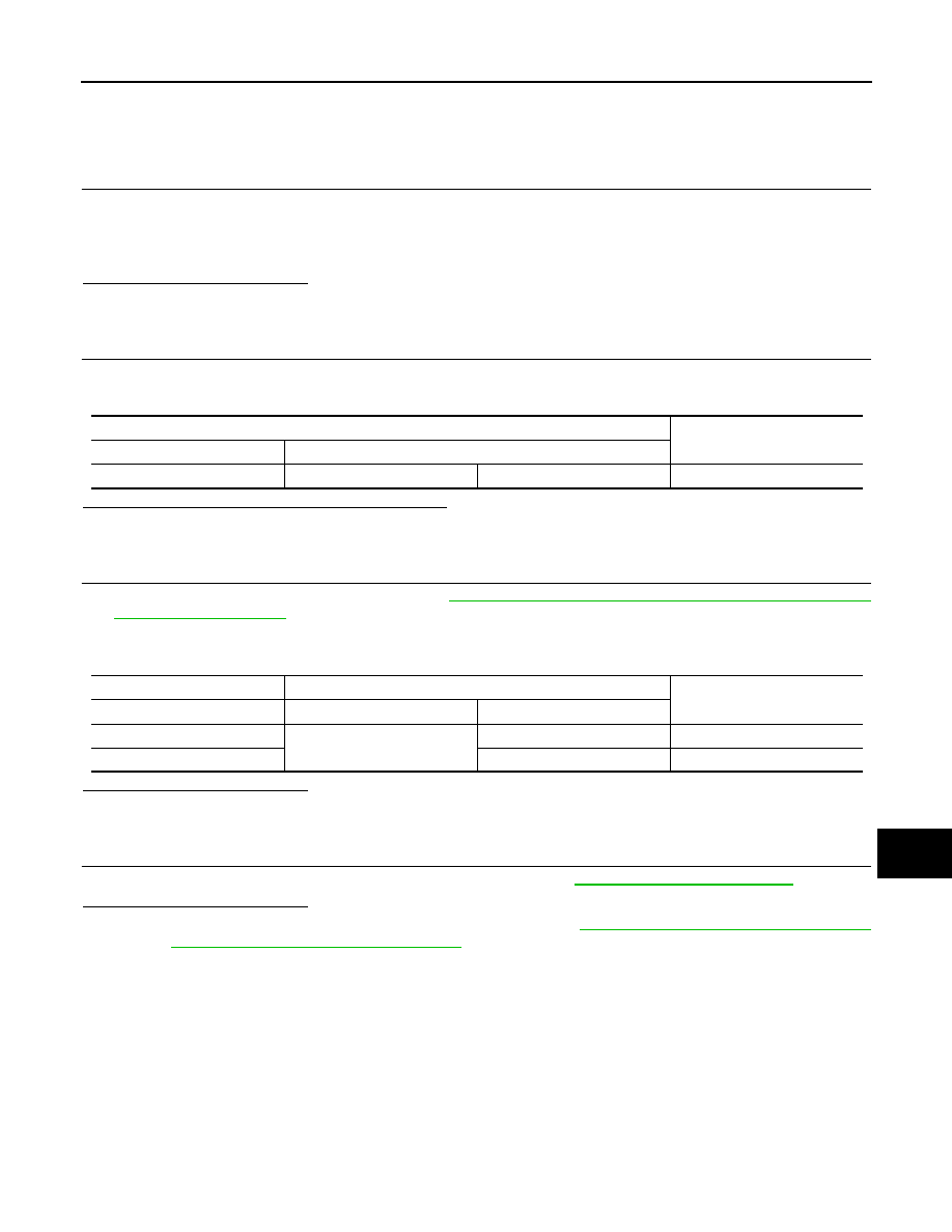
ECM harness connector
Resistance (
Ω)
Connector No.
Terminal No.
E16
94
86
Approx. 108 – 132
LAN
TCM BRANCH LINE CIRCUIT
LAN-73
< COMPONENT DIAGNOSIS >
[CAN]
C
D
E
F
G
H
I
J
K
L
B
A
O
P
N
TCM BRANCH LINE CIRCUIT
Diagnosis Procedure
INFOID:0000000005152919
1.
CHECK CONNECTOR
1. Turn the ignition switch OFF.
2. Disconnect the battery cable from the negative terminal.
3. Check the terminals and connectors of the A/T assembly for damage, bend and loose connection (unit
side and connector side).
Is the inspection result normal?
YES
>> GO TO 2.
NO
>> Repair the terminal and connector.
2.
CHECK HARNESS FOR OPEN CIRCUIT
1. Disconnect the connector of A/T assembly.
2. Check the resistance between the A/T assembly harness connector terminals.
Is the measurement value within the specification?
YES
>> GO TO 3.
NO
>> Repair the TCM branch line.
3.
CHECK HARNESS FOR OPEN CIRCUIT
1. Remove the control valve with TCM. Refer to
TM-172, "Control Valve with TCM and A/T Fluid Tempera-
.
2. Disconnect the connector of TCM.
3. Check the continuity between the A/T assembly connector and the TCM harness connector.
Is the inspection result normal?
YES
>> GO TO 4.
NO
>> Repair the harness between the A/T assembly connector and the TCM harness connector.
4.
CHECK POWER SUPPLY AND GROUND CIRCUIT
Check the power supply and the ground circuit of the TCM. Refer to
Is the inspection result normal?
YES (Present error)>>Replace the control valve with TCM. Refer to
TM-172, "Control Valve with TCM and A/
T Fluid Temperature Sensor 2 and Plug"
YES (Past error)>>Error was detected in the TCM branch line.
NO
>> Repair the power supply and the ground circuit.
A/T assembly harness connector
Resistance (
Ω)
Connector No.
Terminal No.
F9
3
8
Approx. 54 – 66
A/T assembly connector
TCM harness connector
Continuity
Terminal No.
Connector No.
Terminal No.
3
F502
1
Existed
8
2
Existed

LAN-74
< COMPONENT DIAGNOSIS >
[CAN]
LASER BRANCH LINE CIRCUIT
LASER BRANCH LINE CIRCUIT
Diagnosis Procedure
INFOID:0000000005146481
1.
CHECK CONNECTOR
1. Turn the ignition switch OFF.
2. Disconnect the battery cable from the negative terminal.
3. Check the terminals and connectors of the ICC sensor for damage, bend and loose connection (unit side
and connector side).
Is the inspection result normal?
YES
>> GO TO 2.
NO
>> Repair the terminal and connector.
2.
CHECK HARNESS FOR OPEN CIRCUIT
1. Disconnect the connector of ICC sensor.
2. Check the resistance between the ICC sensor harness connector terminals.
Is the measurement value within the specification?
YES
>> GO TO 3.
NO
>> Repair the ICC sensor branch line.
3.
CHECK POWER SUPPLY AND GROUND CIRCUIT
Check the power supply and the ground circuit of the ICC sensor. Refer to
Is the inspection result normal?
YES (Present error)>>Replace the ICC sensor. Refer to
YES (Past error)>>Error was detected in the ICC sensor branch line.
NO
>> Repair the power supply and the ground circuit.
ICC sensor harness connector
Resistance (
Ω)
Connector No.
Terminal No.
E42
2
3
Approx. 54 – 66
Нет комментариевНе стесняйтесь поделиться с нами вашим ценным мнением.
Текст