Infiniti QX56 (JA60). Manual — part 382
EC-180
< COMPONENT DIAGNOSIS >
[VK56DE]
P0172, P0175 FUEL INJECTION SYSTEM FUNCTION
OK or NG
OK
>> GO TO 4.
NG
>> Repair open circuit or short to ground or short to power in harness or connectors.
4.
CHECK FUEL PRESSURE
1. Release fuel pressure to zero. Refer to
2. Install fuel pressure gauge and check fuel pressure. Refer to
OK or NG
OK
>> GO TO 6.
NG
>> GO TO 5.
5.
DETECT MALFUNCTIONING PART
Check the following.
• Fuel pump and circuit (Refer to
• Fuel pressure regulator (Refer to
>> Repair or replace.
6.
CHECK MASS AIR FLOW SENSOR
With CONSULT-III
1. Install all removed parts.
2. Check “MASS AIR FLOW” in “DATA MONITOR” mode with CONSULT-III.
With GST
1. Install all removed parts.
2. Check mass air flow sensor signal in Service $01 with GST.
OK or NG
OK
>> GO TO 7.
NG
>> Check connectors for rusted terminals or loose connections in the mass air flow sensor circuit or
grounds. Refer to
.
7.
CHECK FUNCTION OF FUEL INJECTOR
With CONSULT-III
1. Start engine.
2. Perform “POWER BALANCE” in “ACTIVE TEST” mode with CONSULT-III.
3. Make sure that each circuit produces a momentary engine speed drop.
Without CONSULT-III
1. Start engine.
At idling: Approximately 350 kPa (3.57 kg/cm
2
, 51 psi)
3.0 - 9.0 g·m/sec:
at idling
9.0 - 28.0 g·m/sec:
at 2,500 rpm
3.0 - 9.0 g·m/sec:
at idling
9.0 - 28.0 g·m/sec:
at 2,500 rpm
P0172, P0175 FUEL INJECTION SYSTEM FUNCTION
EC-181
< COMPONENT DIAGNOSIS >
[VK56DE]
C
D
E
F
G
H
I
J
K
L
M
A
EC
N
P
O
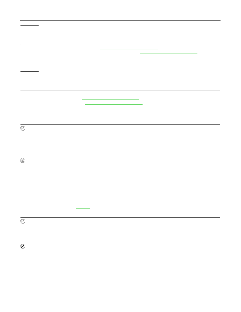
2. Listen to each fuel injector operating sound.
OK or NG
OK
>> GO TO 8.
NG
>> Perform trouble diagnosis for FUEL INJECTOR, refer to
.
8.
CHECK FUEL INJECTOR
1. Remove fuel injector assembly. Refer to
EM-40, "Removal and Installation"
.
Keep fuel hose and all fuel injectors connected to fuel injector gallery.
2. Confirm that the engine is cooled down and there are no fire hazards near the vehicle.
3. Disconnect all fuel injector harness connectors.
4. Disconnect all ignition coil harness connectors.
5. Prepare pans or saucers under each fuel injectors.
6. Crank engine for about 3 seconds.
Make sure fuel does not drip from fuel injector.
OK or NG
OK (Does not drip.)>>GO TO 9.
NG (Drips.)>>Replace the fuel injectors from which fuel is dripping. Always replace O-ring with new one.
9.
CHECK INTERMITTENT INCIDENT
GI-35, "How to Check Terminal"
GI-38, "Intermittent Incident"
>> INSPECTION END
Clicking noise should be heard.
PBIB1986E
EC-182
< COMPONENT DIAGNOSIS >
[VK56DE]
P0181 FTT SENSOR
P0181 FTT SENSOR
Component Description
INFOID:0000000005149196
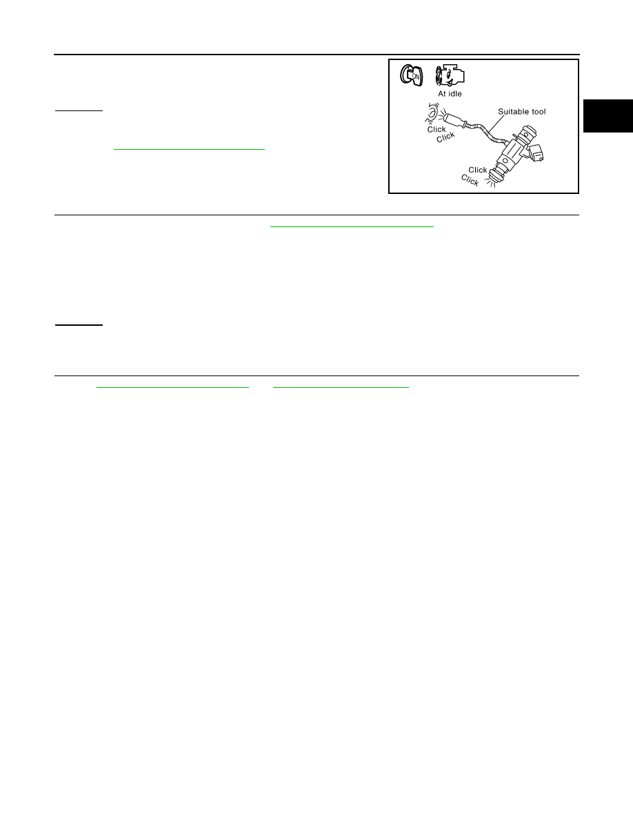
The fuel tank temperature sensor is used to detect the fuel tempera-
ture inside the fuel tank. The sensor modifies a voltage signal from
the ECM. The modified signal returns to the ECM as the fuel temper-
ature input. The sensor uses a thermistor which is sensitive to the
change in temperature. The electrical resistance of the thermistor
decreases as temperature increases.
<Reference data>
*: This data is reference value and is measured between ECM terminal 107 (Fuel
tank temperature sensor) and ground.
CAUTION:
Do not use ECM ground terminals when measuring input/output
voltage. Doing so may result in damage to the ECM's transistor.
Use a ground other than ECM terminals, such as the ground.
On Board Diagnosis Logic
INFOID:0000000005149197
DTC Confirmation Procedure
INFOID:0000000005149198
NOTE:
If DTC Confirmation Procedure has been previously conducted, always perform the following procedure
before conducting the next step.
1. Turn ignition switch OFF and wait at least 10 seconds.
2. Turn ignition switch ON.
3. Turn ignition switch OFF and wait at least 10 seconds.
WITH CONSULT-III
1. Turn ignition switch ON and wait at least 10 seconds.
2. Check 1st trip DTC.
If 1st trip DTC is detected, go to
If 1st trip DTC is not detected, go to following step.
3. Select “DATA MONITOR” mode with CONSULT-III.
4. Check “COOLAN TEMP/S” value.
If the “COOLAN TEMP/S” is less than 60
°C (140°F), the result will be OK.
If the “COOLAN TEMP/S” is above 60
°C (140°F), go to the following step.
5. Cool engine down until “COOLAN TEMP/S” signal is less than 60
°C (140°F).
BBIA0583E
Fluid temperature
°C (°F)]
Voltage*
(V)
Resistance
(k
Ω)
20 (68)
3.5
2.3 - 2.7
50 (122)
2.2
0.79 - 0.90
SEF012P
DTC No.
Trouble diagnosis name
DTC detecting condition
Possible cause
P0181
0181
Fuel tank temperature
sensor circuit range/per-
formance
Rationally incorrect voltage from the sensor is
sent to ECM, compared with the voltage signals
from engine coolant temperature sensor and in-
take air temperature sensor.
• Harness or connectors
(The sensor circuit is open or shorted)
• Fuel tank temperature sensor
P0181 FTT SENSOR
EC-183
< COMPONENT DIAGNOSIS >
[VK56DE]
C
D
E
F
G
H
I
J
K
L
M
A
EC
N
P
O
6. Wait at least 10 seconds.
7. Check 1st trip DTC.
8. If 1st trip DTC is detected, go to
WITH GST
Follow the procedure “WITH CONSULT-III” above.
Diagnosis Procedure
INFOID:0000000005149199
1.
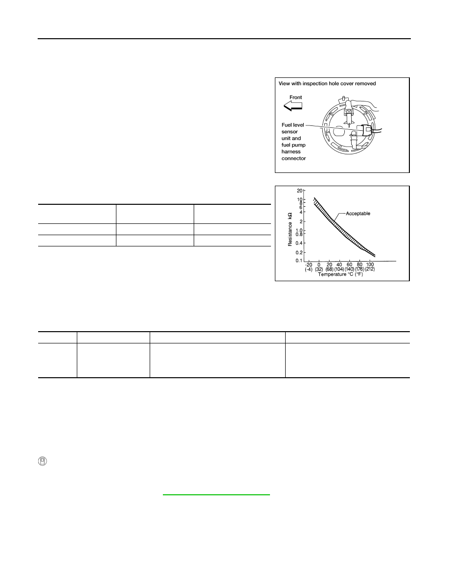
CHECK FUEL TANK TEMPERATURE SENSOR POWER SUPPLY CIRCUIT
1. Turn ignition switch OFF.
2. Disconnect “fuel level sensor unit and fuel pump” harness con-
nector.
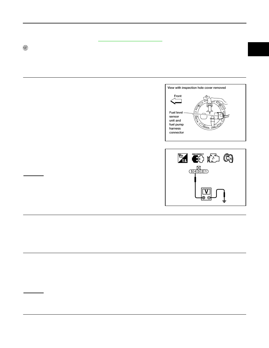
3. Turn ignition switch ON.
4. Check voltage between “fuel level sensor unit and fuel pump”
terminal 4 and ground with CONSULT-III or tester.
OK or NG
OK
>> GO TO 3.
NG
>> GO TO 2.
2.
DETECT MALFUNCTIONING PART
Check the following.
• Harness connectors C1, E41
• Harness for open or short between ECM and “fuel level sensor unit and fuel pump”
>> Repair harness or connector.
3.
CHECK FUEL TANK TEMPERATURE SENSOR GROUND CIRCUIT FOR OPEN AND SHORT
1. Turn ignition switch OFF.
2. Check harness continuity between “fuel level sensor unit and fuel pump” terminal 3 and ground. Refer to
Wiring Diagram.
3. Also check harness for short to power.
OK or NG
OK
>> GO TO 5.
NG
>> GO TO 4.
4.
DETECT MALFUNCTIONING PART
Check the following.
• Harness connectors C1, E41
• Harness for open or short between “fuel level sensor unit and fuel pump” and ground
BBIA0583E
Voltage: Approximately 5 V
PBIB0932E
Continuity should exist.
Нет комментариевНе стесняйтесь поделиться с нами вашим ценным мнением.
Текст